Method for operating a transmission device with a plurality of friction-locking and positive-locking shifting elements

一种换挡元件、摩擦锁合的技术,应用在运输和包装、带有齿的元件、多传动比传动装置等方向,能够解决降低驾驶舒适性的换挡噪音、剧烈刹车等问题,达到高舒适性的效果

Active Publication Date: 2012-02-29
ZF FRIEDRICHSHAFEN AG
View PDF8 Cites 10 Cited by
  • Summary
  • Abstract
  • Description
  • Claims
  • Application Information

AI Technical Summary

Problems solved by technology

[0007] However, the problem with the above-mentioned transmission device is that the spontaneous gradient of the transmission input speed or the equivalent speed variable cannot be taken into account to the desired extent after the moment of the shift request of the shifting element for engaging the positive lock. change, such as a spontaneous change caused, for example, by a sharp change in the position of the vehicle's accelerator pedal or by heavy braking of the vehicle on the driver's side
If the engagement of the form-fitting shifting elements is carried out outside the desired speed difference range, shifting noises occur which reduce driving comfort and the driver also experiences a torque reaction in the form of jerks in the drivetrain

Method used


Image

  • Method for operating a transmission device with a plurality of friction-locking and positive-locking shifting elements
  • Method for operating a transmission device with a plurality of friction-locking and positive-locking shifting elements
  • Method for operating a transmission device with a plurality of friction-locking and positive-locking shifting elements

Examples


Embodiment Construction

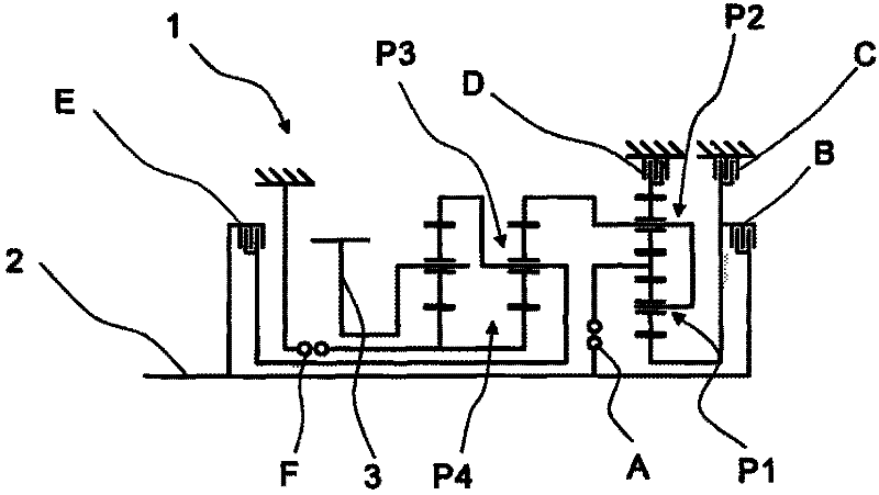
[0026] figure 1 A schematic representation of the gears of the transmission arrangement 1 or of a multi-stage transmission is shown, which is known in principle from the unpublished German patent application DE 102008000429.4 of the same applicant. The transmission device 1 comprises a drive shaft 2 , which is connected to the output end of the vehicle when installed in the vehicle, and a driven shaft 3 , which is operatively connected to the drive machine.

[0027] Furthermore, the transmission device 1 comprises four planetary gearsets P1 to P4, wherein the first and second planetary gearsets P1, P2, which are preferably designed as negative planetary gearsets, form a shiftable front gearset, while the third and The fourth planetary gear set P3, P4 constitutes the main gear set. The transmission device 1 additionally comprises six shifting elements A to F, wherein the shifting elements B, D and E are designed as brakes and the shifting elements A, C and F are designed as sh...


PUM


Abstract

A method is described for operating a transmission device (1) with a plurality of friction-locking and positive-locking shifting elements (A to F) for obtaining different gears. A shift request to close a positive-locking shifting element (F) undergoes a time delay dependent on operational state prior to the connection time of the positive-locking shifting element, wherein a rotational speed differential between the halves of the shifting element of the positive-locking shifting element (F) is provided for the connection time within a rotational speed differential window required for the engagement. According to the invention, a gradient of the transmission input speed or an equivalent rotational speed value is detected at the time of the shift request and the actual gradient is subsequently monitored and also compared to the gradients at the time of the shift request. When a maximum deviation greater than a threshold value is detected, the period of time is changed or an actuation of a friction-locking shifting element to be disconnected is varied to an extent that reduces the deviation below the threshold value.

Description

technical field [0001] The invention relates to a method for operating a transmission arrangement comprising a plurality of friction-locking shifting elements and positive-locking shifting elements according to the type further defined in the preamble of claim 1 . Background technique [0002] In automatic transmissions known from practice that have both friction-fitting and form-fitting shifting elements to obtain a plurality of different gear ratios, the shifting mechanism for closing the form-fitting connection by means of the application of force The gear command is triggered by means of the transmission control unit or the transmission software running in the transmission control unit with a certain time advance before the synchronization point of the form-fitting shifting elements is reached. [0003] The timing advance is also largely influenced by the operating temperature of the transmission oil, especially in the case of hydraulically actuated form-locking shifting...

Claims


Application Information

Patent Timeline
Patent Type & Authority Applications(China)
IPC IPC(8): F16H61/08F16H61/04F16H61/686
CPCF16H61/0403F16H61/0437F16H61/08F16H61/686F16H2003/442F16H2061/0474F16H2200/0065F16H2200/2012F16H2200/2046F16H2200/2064F16H2059/425F16H2200/2094F16H3/666F16H61/04
Inventor J·阿诺尔德V·埃贝特G·米哈奇
Owner ZF FRIEDRICHSHAFEN AG
Why Eureka
Try Eureka