Cyclone type dust collecting unit

A dust collection device, cyclone technology, applied in the field of dust collection devices, can solve the problems of inconvenience to consumers, increase the cost of use, and failure to prevent microbial reproduction, etc., and achieve the effects of reducing trouble, preventing pollution, and reducing costs

Inactive Publication Date: 2005-03-30
LG ELECTRONICS (TIANJIN) APPLIANCES CO LTD
View PDF0 Cites 2 Cited by
  • Summary
  • Abstract
  • Description
  • Claims
  • Application Information

AI Technical Summary

Problems solved by technology

[0021] Because there is no structure to prevent the reproduction of microorganisms, it will have a bad effect if it stays for a long time
[0022] Therefore, just need often to filter paper 26 be cleaned up, bring inconvenience to consumer
[0023] In particular, the filter paper 26 is made of paper, so it needs to be replaced frequently, which increases the cost of use.

Method used


Image

  • Cyclone type dust collecting unit
  • Cyclone type dust collecting unit
  • Cyclone type dust collecting unit

Examples


Embodiment Construction

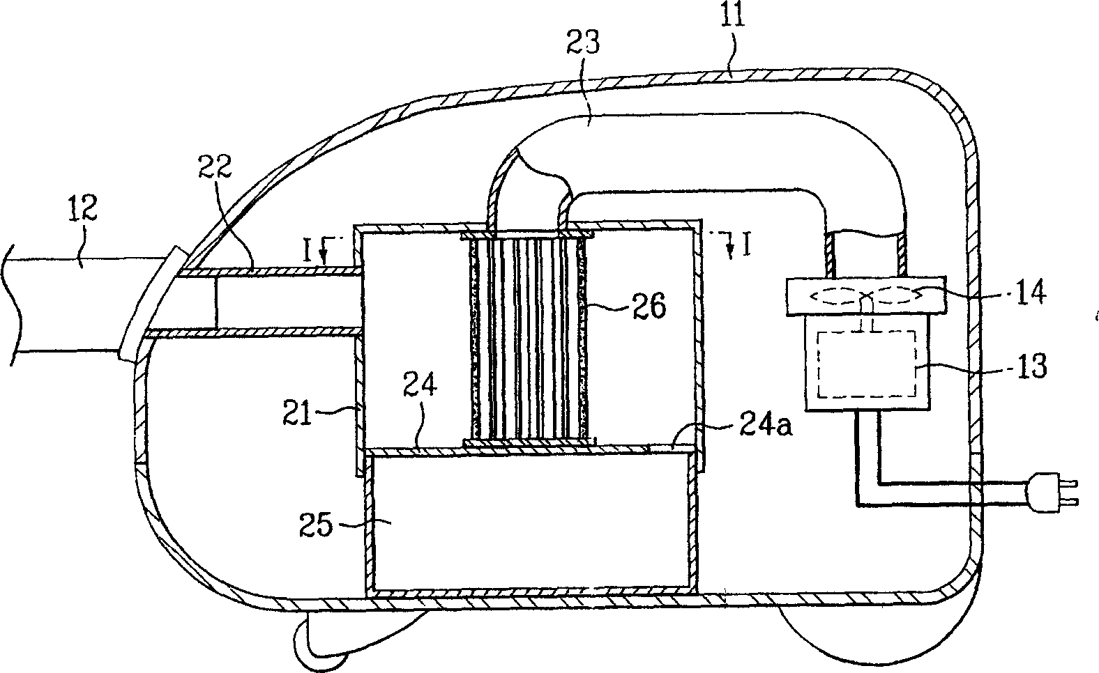
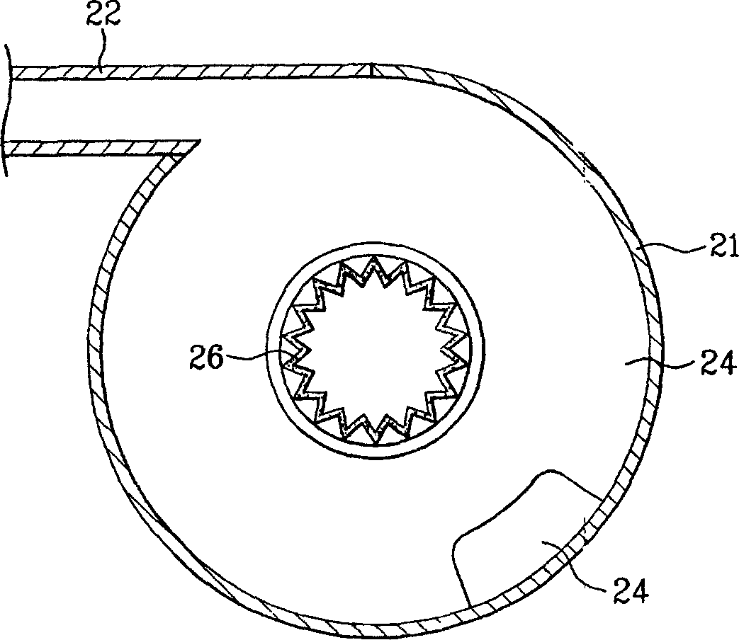
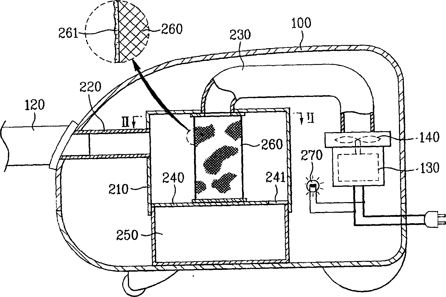
[0046] Below in conjunction with accompanying drawing and specific embodiment the present invention is described in further detail: image 3 A longitudinal sectional view showing an embodiment of the cyclone vacuum cleaner of the present invention. Figure 4 yes image 3 The II-II line profile.

[0047] As can be seen from the drawings, the cyclone vacuum cleaner of the present invention includes a vacuum cleaner body 11 having a drive motor 13 and a fan 14, a cyclone housing 21, an air inflow pipe 22, an air discharge pipe 23, a filter body 260 and a light source irradiation part.

[0048] The cyclone housing 21 is arranged inside the vacuum cleaner body 11 and is roughly cylindrical.

[0049] The air inflow pipe 22 communicates with the suction hose 12 connected to the vacuum cleaner body 11 , and the other end side passes through the upper outer peripheral surface of the cyclone housing 21 and communicates with the inner space of the cyclone housing 21 .

[0050] The air...


PUM


Abstract

A cyclone dust collector able to prevent the pollution of microbes to filter is composed of a main body with motor and fan, a cyclone casing, an air inlet pipe, an air outlet pipe, a filter whose surface is coated by photocatalyst, and light source.

Description

technical field [0001] The invention relates to the field of dust collecting devices. Background technique [0002] Generally speaking, a cyclone-type dust collection device is used on the vacuum cleaner body. The cyclone-type dust collection device uses the principle of a cyclone to separate and collect foreign objects that rotate with the air when the air is discharged to the outside. [0003] figure 1 It is a longitudinal sectional view showing a conventional cyclone vacuum cleaner. figure 2 express figure 1 I-I line profile. [0004] The cyclone vacuum cleaner includes the following structures: a cyclone housing 21 provided inside the cleaner body 11 , and a cyclone dust collecting part including an air inflow pipe 22 and an air discharge pipe 23 . [0005] The cyclone casing 21 constituting the cyclone dust collecting unit is cylindrical. [0006] The bottom space of the cyclone housing 21 forms a dust collection space 25 for collecting foreign matter through the ...

Claims


Application Information

Patent Timeline
Patent Type & Authority Applications(China)
IPC IPC(8): A47L9/16A61L2/00
Inventor 郑回吉
Owner LG ELECTRONICS (TIANJIN) APPLIANCES CO LTD
Why Eureka
Try Eureka