

Heat carrier set in blowout prevention type
A carrier and integrated technology, applied in the field of heat carrier heating system, can solve problems such as interrupting normal operation, threatening the life safety of operators, polluting the environment, etc., to achieve the effect of preventing pollution, ensuring normality and safety
- Summary
- Abstract
- Description
- Claims
- Application Information
AI Technical Summary
Problems solved by technology
Method used
Image

Examples
Embodiment Construction
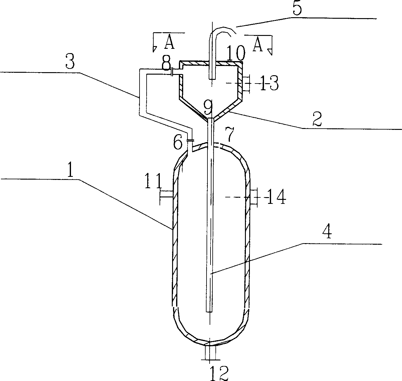
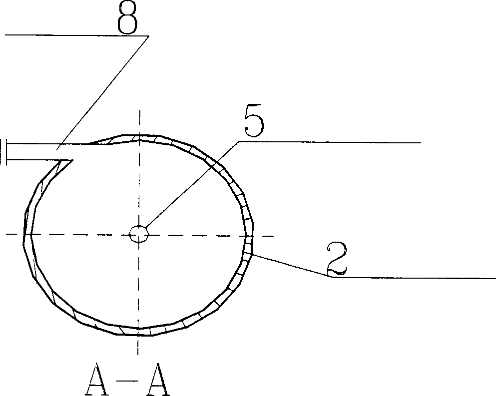
[0012] Such as figure 1 with figure 2 Shown, the present invention is to set up an oil-vapor centrifugal separation system on the existing conventional heat carrier tank 1. The system includes a centrifugal oil vapor separation tank 2 , an oil vapor outlet pipe 3 , an oil return pipe 4 and a water vapor emptying pipe 5 . The oil vapor separation tank 2 is located on the top of the heat carrier tank 1, and is integrated with the heat carrier tank 1 through an oil vapor outlet pipe 3 and an oil return pipe 4. Wherein the oil-vapor outlet pipe 3 is connected with the upper opening 6 of the heat carrier tank 1 through the opening 8 on the upper end of the oil-vapor separation tank 2, and the opening 8 enables the heat carrier to flow from the oil-vapor outlet pipe through the upper opening 6 of the heat carrier tank 1. 3 enters the oil-vapor separation tank 2 in a tangential way; the bottom of the oil-vapor separation tank 2 is connected to the top of the heat carrier tank 1 b...
PUM
| Property | Measurement | Unit |
|---|---|---|
| Cone angle | aaaaa | aaaaa |
Abstract
Description
Claims
Application Information