LCD modular and polarized optical brightening membrane

A technology of liquid crystal display module and brightness enhancement film, which is applied in the directions of optics, polarizing elements, nonlinear optics, etc., and can solve the problems of poor light source utilization rate of liquid crystal display module 1, etc.

Active Publication Date: 2005-03-30
AU OPTRONICS CORP
View PDF3 Cites 16 Cited by
  • Summary
  • Abstract
  • Description
  • Claims
  • Application Information

AI Technical Summary

Problems solved by technology

[0003] in such as figure 1 In the shown liquid crystal display module 1, the light emitted by the light source 25 of the backlight (backlight) module 20 will usually ...

Method used


Image

  • LCD modular and polarized optical brightening membrane
  • LCD modular and polarized optical brightening membrane
  • LCD modular and polarized optical brightening membrane

Examples


Embodiment Construction

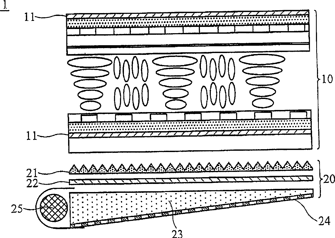
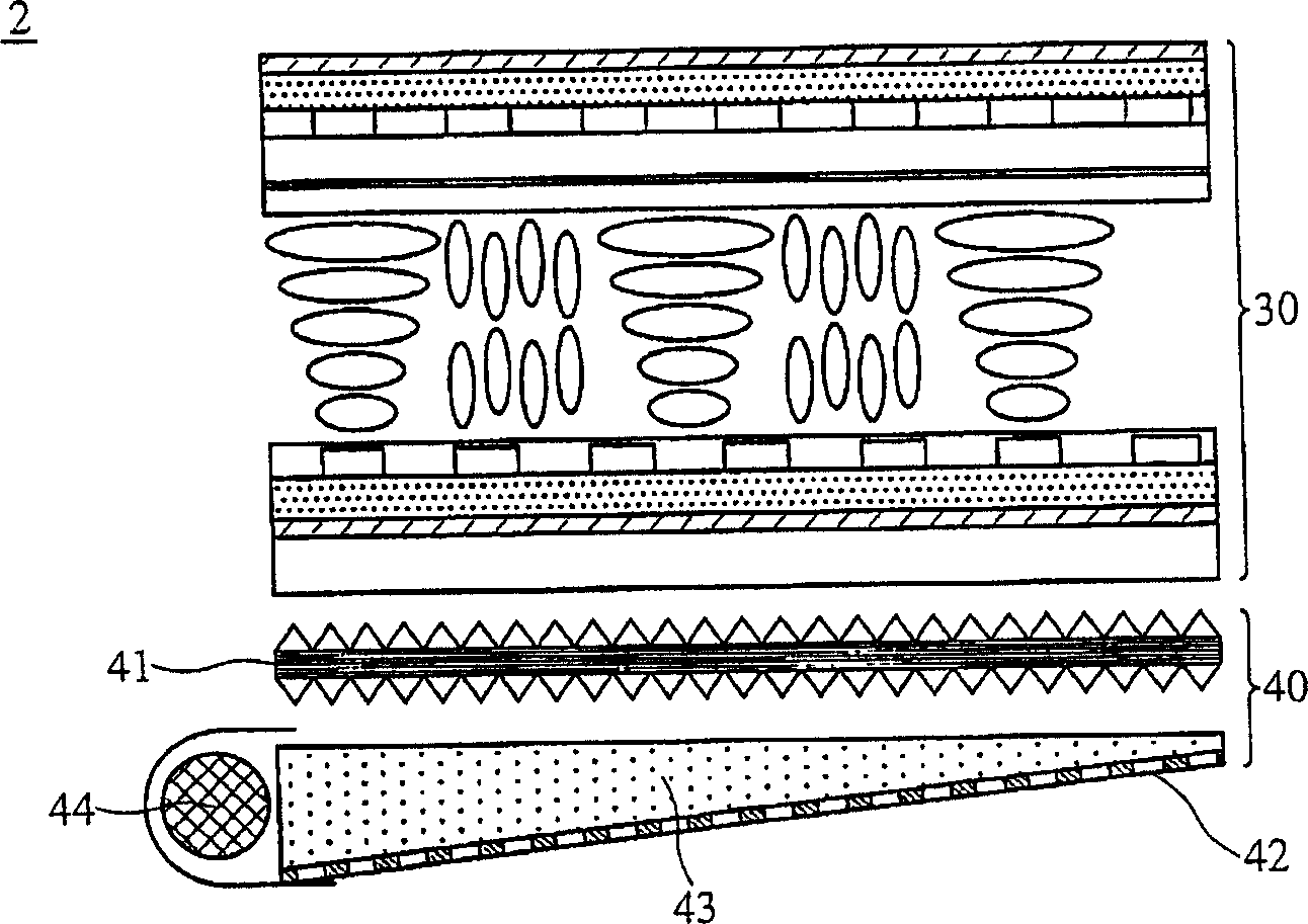
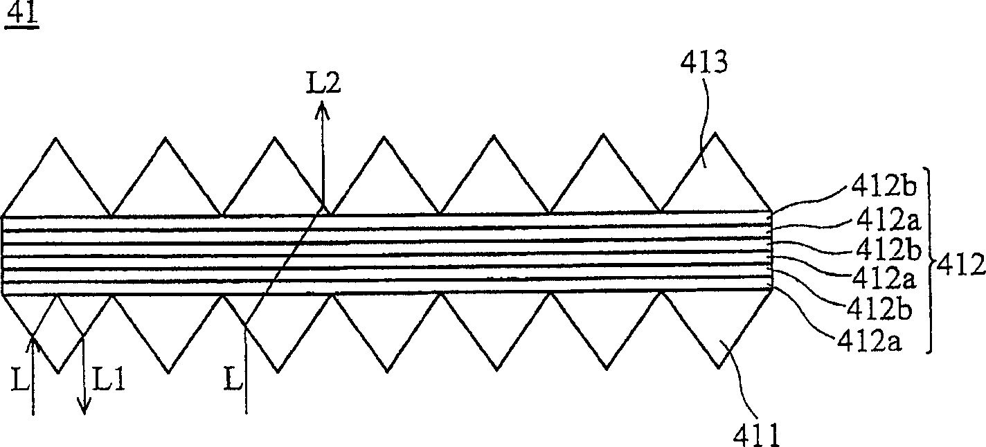
[0035] refer to figure 2 , the structure of the liquid crystal display module 2 of the present invention and figure 1 The known liquid crystal display module 1 shown is similar, including a backlight module 40 and a liquid crystal panel 30, wherein the liquid crystal panel 30 is arranged on the backlight module 40, and the backlight module 40 includes a polarized optical brightness enhancement film 41, a light guide plate 42 , a reflector 43, and a light source 44; it should be understood that the liquid crystal display module also includes other components, since it has nothing to do with the present invention, its description is omitted here; in addition, in this embodiment, the same as the known Components are also omitted in their detailed description.

[0036] Compare figure 2 with figure 1 It can be seen that the difference between the liquid crystal display module 2 of this embodiment and the known liquid crystal display module 1 is: in this embodiment, the polariz...


PUM


Abstract

The invention relates to a liquid crystal display module and its polarized optical brightening film, in which the polarized optical brightening film includes a first prism, a thin-film and a second prism. Said thin-film is placed on first prism, and has at least a first refraction layer and at least a second refraction layer, the first refraction layer is different from second refraction layer in index of refraction, and the thickness of every first refraction layer and every second refraction layer is lambda o/4n, and the light source which is incident from first pirsm can be divided into S polarized light and P polarized light, the S polarized light can be reflected to first pirsm by means of thin-film so as to prevent said S polarized light from being absorbed by polaroid, the second prism is placed on the thin-film, and the P polarized light can be transmitted through the thin- film and income to second prism,

Description

technical field [0001] The invention relates to a polarized optical brightness enhancement film, in particular to a polarized optical brightness enhancement film which can effectively increase the optical utilization rate of a liquid crystal display module. Background technique [0002] refer to figure 1 , which is a schematic diagram of a liquid crystal display module 1 of a known thin film transistor liquid crystal display (TFT-LCD), wherein the symbol 10 represents a liquid crystal panel, and the symbol 20 represents a backlight module, and the liquid crystal panel 10 is usually provided with two polarizers 11, a backlight module 20 It includes a prism 21 , an optical film 22 , a light guide plate 23 , a reflector 24 , and a light source 25 . It should be understood that in the known backlight module 20 , the prism 21 is used for light collection. [0003] in such as figure 1 In the shown liquid crystal display module 1, the light emitted by the light source 25 of the b...

Claims


Application Information

Patent Timeline
IPC IPC(8): G02B5/04G02B5/30G02F1/1335
Inventor 郗任远陈永寿高忠诚
Owner AU OPTRONICS CORP
Why Eureka
Try Eureka