Diaphragm pump structure for improving assembling reliability

A diaphragm pump and diaphragm technology, applied in the field of improved structure of the diaphragm pump, can solve the problems of easy loosening from the body 7, wear and installation of the diaphragm pump 11, and difficulty in separation.

Inactive Publication Date: 2005-04-06
KYOSAN DENKI KABUSHIKI KAISHA +1
View PDF0 Cites 4 Cited by
  • Summary
  • Abstract
  • Description
  • Claims
  • Application Information

AI Technical Summary

Problems solved by technology

However, crimping causes difficulties during the disassembly of the diaphragm pump 6, that is, the separation of the individual parts into different material types
[0010] To avoid this problem, the cover 12 can be screwed onto the body 7, however, it encounters other problems, namely, since the cover 12 is made of resin and the diaphragm pump 11 is made of rubber, rotating the cover 12 to Fixing it to the body 7 will cause the diaphragm pump 11 to rotate with the rotation of the cover 12, which can cause wear of the diaphragm pump 11 or errors in the installation of the diaphragm pump 11, and screwing makes the cover 12 easy to remove from the body 7 Therefore, once the cover 12 is removed from the body 7, it will cause rupture of the diaphragm pump 11 or incorrect reassembly of the diaphragm pump 11

Method used


Image

  • Diaphragm pump structure for improving assembling reliability
  • Diaphragm pump structure for improving assembling reliability
  • Diaphragm pump structure for improving assembling reliability

Examples


Embodiment Construction

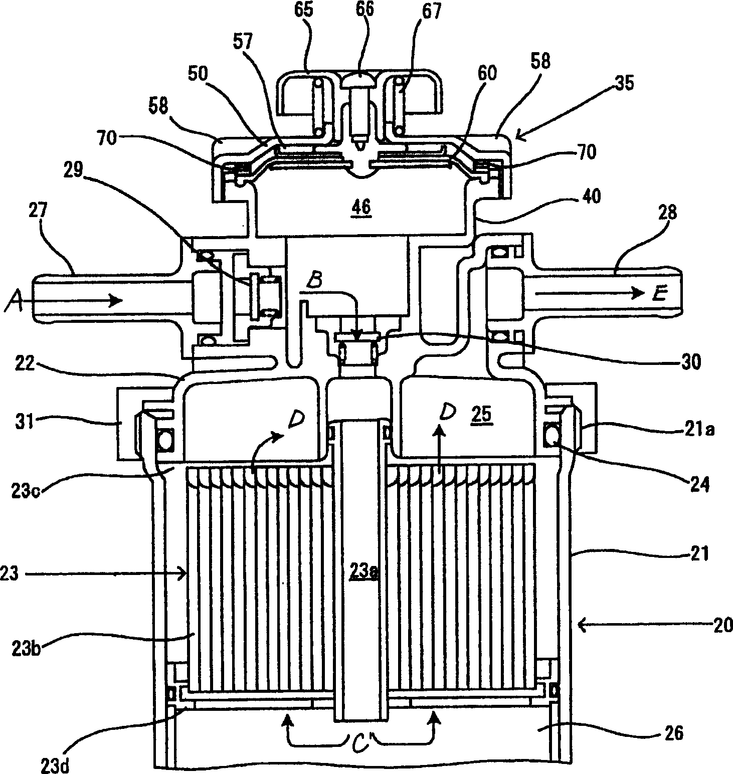
[0041] Referring to the drawings, in which like reference numerals designate like parts throughout the several views, and in particular figure 1 , which shows a diaphragm pump 35 provided with a diesel filter 20 according to the invention, which can be installed in the fuel system of an automotive diesel engine.

[0042] The diesel filter 20 includes a cup-shaped housing 21 defining an outer shell, a cap 22 detachably mounted at an open end of the housing 21 , and a filter device 23 placed inside the housing 21 .

[0043] The casing 21 is made of a resinous hollow cylinder with an upper opening. On the outer circumference of the upper end of the housing 21, a thread 21a is cut.

[0044] The filter device 23 is composed of a fuel path pipe 23a, a filter element 23b, an upper end plate 23c with holes (not shown) and a lower end plate 23d with holes (not shown), wherein the fuel path pipe 23a is coaxial with the The rolled sheet (or sheets) forms the filter element 23b. A fuel ...


PUM


Abstract

The invention provides a diaphragm pump device. The diaphragm pump device is provided with the body forming an outline, and having an opening at an end, the diaphragm closing the opening of the body, and forming a pumping chamber in the body, a cover member installed at the opposite side to the diaphragm and forming an atmospheric chamber inside. The body and the cover member are fastened with a screw to hold the diaphragm narrowly. A corotation preventing member is interposed in the narrow position of the diaphragm with the body and the cover member.

Description

technical field [0001] The present invention relates to a diaphragm pump used in a fuel filter of an automobile diesel engine, in particular to an improved structure of the diaphragm pump for improving its assembly reliability. Background technique [0002] Figure 17 A typical common line (common rail) fuel system for an automotive diesel engine is shown. The fuel system basically consists of an injection pump 1 , a utility line 2 , an injector 3 (only one is shown for brevity), a fuel tank 4 and a diesel filter 5 . The injection pump 1 operates to supply pressurized fuel to the common line 2, which in turn is injected from the injectors 3 stored in the individual cylinders of the engine. The black arrows indicate the flow of fuel from the fuel tank 4 to the injector 3 . The white arrows indicate the flow of fuel back from the injector 3 to the fuel tank 4 . [0003] Usually, fuel oil is mixed with impurities such as dust, rust, carbon, sludge and water vapor, and these ...

Claims


Application Information

Patent Timeline
Patent Type & Authority Applications(China)
IPC IPC(8): F02M37/16F04B43/02
CPCF04B43/02
Inventor 泽田一人柳光则森下浩
Owner KYOSAN DENKI KABUSHIKI KAISHA
Why Eureka
Try Eureka