
Unified electric energy quality controller

A power quality and controller technology, applied in electrical components, circuit devices, AC network circuits, etc., can solve problems affecting system power quality, harmonic current distortion, etc.

Inactive Publication Date: 2005-04-06
北京思源清能电气电子有限公司
View PDF1 Cites 11 Cited by
  • Summary
  • Abstract
  • Description
  • Claims
  • Application Information

AI Technical Summary

Problems solved by technology

On the other hand, the diversity of loads, especially the use of power electronic rectification or other nonlinear loads, causes current distortion including harmonics, which seriously affects the power quality of the system

Method used


Image

  • Unified electric energy quality controller
  • Unified electric energy quality controller
  • Unified electric energy quality controller

Examples


Embodiment Construction

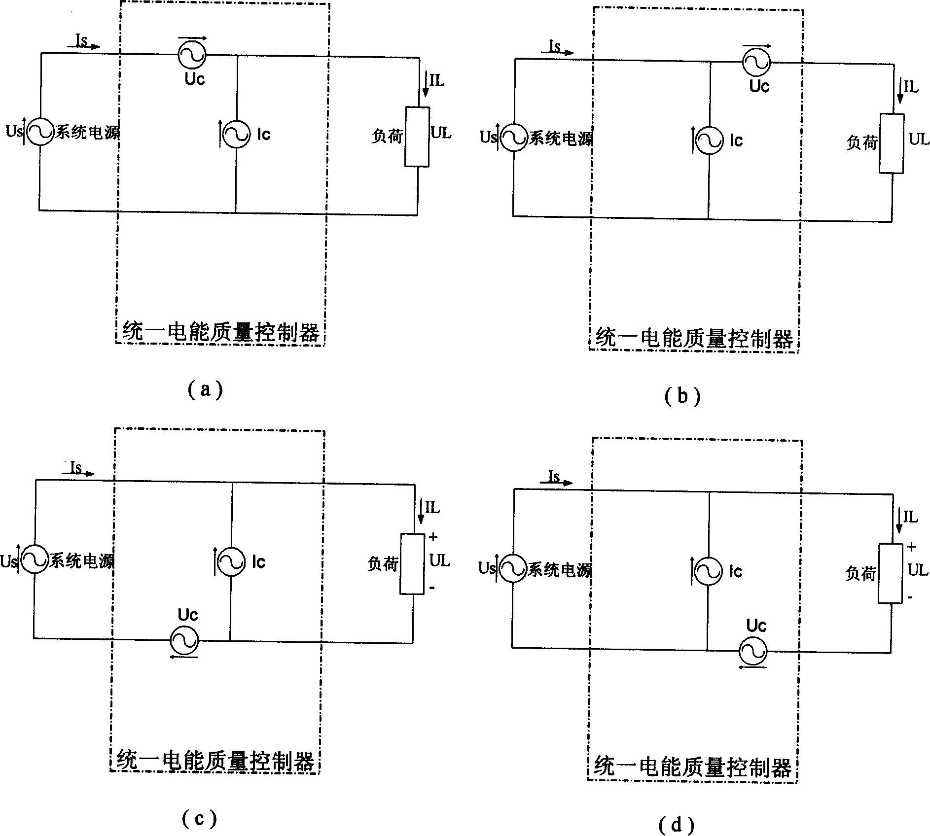
[0028] figure 1 It is a schematic diagram of the working principle of the unified power quality controller (UPQC). Such as figure 1 As shown, the unified power quality controller can be regarded as a combination of a voltage source (represented by Uc) and a current source (represented by Ic); the voltage source is connected in series between the power supply system and the user load; the current The power source is connected in parallel with the power supply system and user load; that is, when a voltage quality problem occurs in the power supply system, the voltage source provides the compensation voltage required by the user load; when a current quality problem occurs in the power supply system or user load, the The current source provides the current required by the user load or the power supply system; when the voltage quality problem and the current quality problem occur in the power supply system at the same time, the voltage source and the current source provide the power...


PUM


Abstract

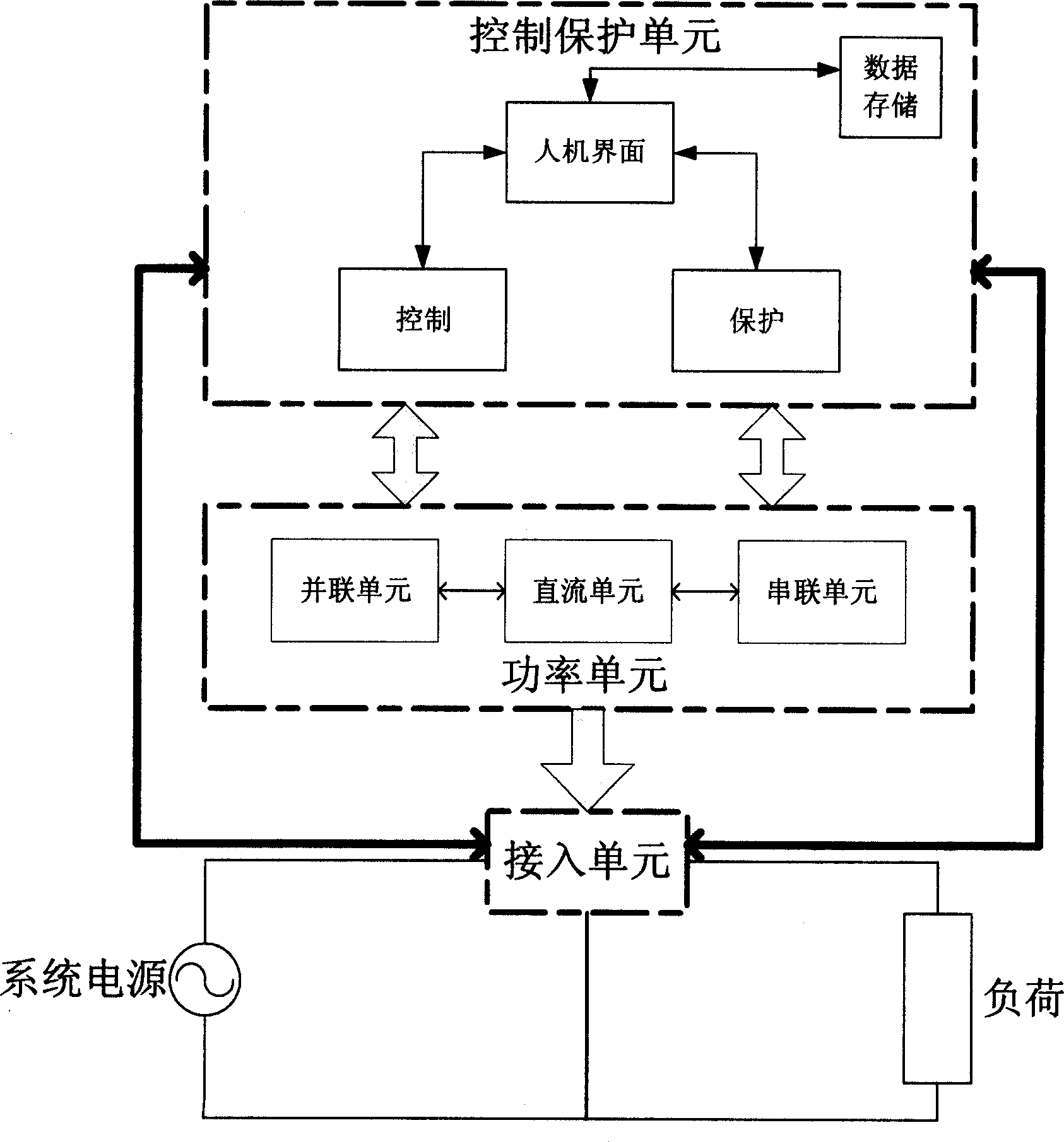
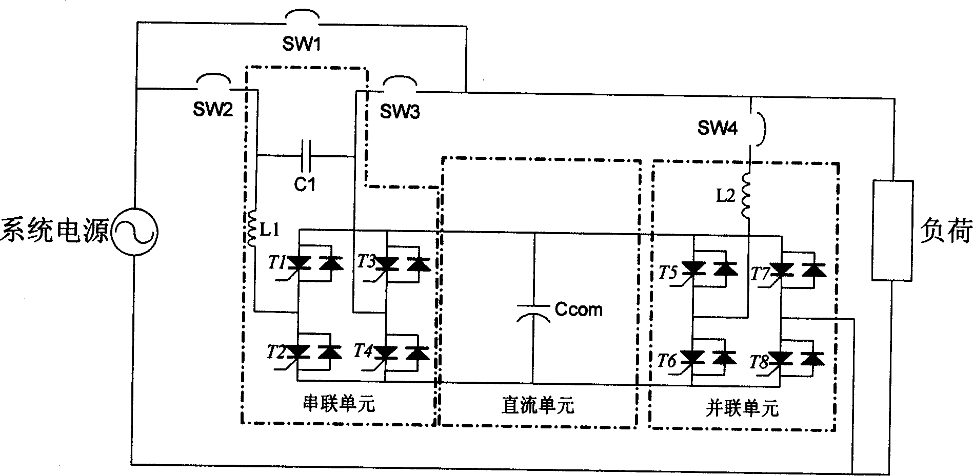
This invention discloses a power quality controller comprising control and protects unit, power unit and input unit. The power unit in this invention comprises parallel unit, serial unit and direct unit. The function of the controller is to cascade a voltage and parallel connect a current source in system alignment circuit. It is an integration improvement for power quality apparatus to the load.

Description

Technical field [0001] The present invention belongs to the power electronic technology of power system, and more specifically relates to a power quality control device between AC power supply and AC power reception in the power system, and particularly relates to a unified power quality control device. Background technique [0002] Power quality generally refers to the deviation of the voltage or current amplitude, frequency, waveform and other parameters from the specified value. [0003] Power quality problems have a wide range, but they can be divided into two major categories: voltage quality problems and current quality problems. In actual systems, voltage and current are closely related. Although the alternating current generated by the generator is basically a sinusoidal waveform, when the current passes through the system impedance, a voltage drop will occur, causing the load-side voltage to suffer interference. For example: the short-circuit current generated by the sho...

Claims


Application Information

Patent Timeline
IPC IPC(8): H02J3/00
Inventor 姜齐荣沈斐虞苍壁黄炜
Owner 北京思源清能电气电子有限公司
Learn More