Sewing machine

A sewing machine and needle technology, which is applied to sewing machine components, sewing machine needle holders, sewing machine thread take-up devices, etc., to achieve the effects of improving reliability, preventing machine needles from falling off, and preventing poor sewing

Inactive Publication Date: 2005-04-20
JUKI CORP
View PDF1 Cites 8 Cited by
  • Summary
  • Abstract
  • Description
  • Claims
  • Application Information

AI Technical Summary

Problems solved by technology

[0011] The object of the present invention is to solve the problem of preventing the upper thread from coming out of the needle at the beginning of sewing

Method used


Image

  • Sewing machine
  • Sewing machine
  • Sewing machine

Examples


no. 2 Embodiment

[0107] The second embodiment of the position change mechanism is for example Figure 5 shown.

[0108] In the present embodiment, the structure other than the position changing mechanism 30A is the same as that of the sewing machine 10, and thus redundant description will be omitted.

[0109] Should Figure 5 It is a plan view of the position changing mechanism 30A, and its arrangement on the sewing machine is different from the position changing mechanism 30 in that it is supported on an unillustrated frame near the outer side of the table 11 .

[0110] That is, the position change mechanism 30A has: a link body 32A supported by a frame capable of swinging in the vertical direction as a center, an engaging member 31A fixed to the base of the link body 32A, and a mechanism for giving the link body 32A a swinging action. Drive mechanism.

[0111] The engaging member 31A swings along with the swing of the link body 32A, and its front end portion is formed in a key shape. In ...

no. 3 Embodiment

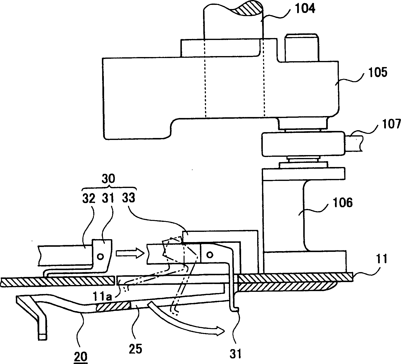
[0116] The third embodiment of the position change mechanism is for example Image 6 shown.

[0117] In this embodiment, it is not necessary to provide the elongated hole 25 in the rotary thread take-up lever 20, and the structure other than the position changing mechanism 30B is the same as that of the sewing machine 10, so repeated description will be omitted.

[0118] Should Image 6 It is a front view of the sewing machine 10B having the position changing mechanism 30B.

[0119] The position changing mechanism 30B has: a link body 32B supported by the frame so as to be swingable in the horizontal direction (direction parallel to the upper shaft 104), an engaging member 31B fixedly supported on the base of the link body 32B, and a The link body 32B is a motor 33B as a drive mechanism that swings.

[0120] Hook up part 31B, swing along with the swing of link body 32B, its front end portion is bent to this face side, so that can be with the face ( Image 6 The surface sho...

no. 4 Embodiment

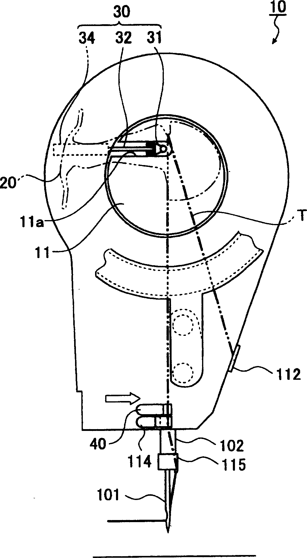
[0125] The fourth embodiment of the position changing mechanism is for example Figure 7 shown.

[0126] In this embodiment, it is not necessary to provide the elongated hole 25 in the rotary thread take-up lever 20, and the structure other than the position change mechanism is the same as that of the sewing machine 10, so repeated description will be omitted.

[0127] Should Figure 7 It is a front view of 10C of sewing machines with a position changing mechanism.

[0128] The position change mechanism is substantially on the same plane as the platen 11, and is arranged between the thread guide 112 and the rotary thread take-up lever 20, and has the following features: it is supported to move up and down along the notch provided on the frame The engagement member 31C and a drive mechanism such as a solenoid (not shown) for switching the engagement member 31C between the upper and lower positions.

[0129] The engaging member 31C moves substantially vertically upward from t...


PUM


Abstract

PROBLEM TO BE SOLVED: To suppress the dropping of a needle thread from a sewing needle at the time of the starting of sewing.

SOLUTION: This sewing machine 10 is equipped with a rotary needle thread take up member 20 which is arranged on the upstream side of the sewing needle 101 on a thread needle pathway, and at the same time, imparts a tension which periodically changes by the same cycle as the vertical movement of the sewing needle 101 to the needle thread. The rotary needle thread take up member 20 is equipped with a base section 21 which becomes the pivot side, and an arm section 22 which makes the needle thread T reciprocate in the longitudinal direction by rotating as it remains spanned with the needle thread T. A recess section 23 in which the needle thread T drops from the needle take up upper dead point position 26 of the needle thread T is provided on the arm section 22. The rotary needle thread take up member 20 is constituted by having a needle thread position changing means 30 which moves the needle thread T to the recess section 23 before a first stitch is formed.

COPYRIGHT: (C)2005,JPO&NCIPI

Description

technical field [0001] The invention relates to a rotary thread take-up sewing machine. Background technique [0002] Figure 10 is a front view of a conventional rotary take-up sewing machine 100, Figure 11 Yes Figure 10 The X-X section view, Figure 12 is a side view. This conventional sewing machine 100 has: a needle bar 102 holding a machine needle 101 at its lower end; Upper shaft 104, torque fluctuation canceling weight 105 installed at the front end of upper shaft 104, needle bar crank 106 eccentrically installed on weight 105, needle bar crank 106 and needle bar 102 are connected to transmit vertical driving force The needle bar crank rod 107, the table plate 108 fixedly installed on the front end side of the needle bar crank 106, and the rotating thread take-up lever 109 fixedly supported on the table plate 108 (for example, refer to Patent Document 1). [0003] This sewing machine 100 further includes: a first thread tensioner 110 for applying a predetermined...

Claims


Application Information

Patent Timeline
Patent Type & Authority Applications(China)
IPC IPC(8): D05B49/04D05B19/00D05B19/02D05B57/00
CPCD05B19/04D05B47/04D05B49/04D05B55/14D05B57/30D05B69/10D05B69/30
Inventor 秋山辰仁
Owner JUKI CORP
Why Eureka
Try Eureka