Disk drive having reduced variation of disk surface lubricant layer thickness

A disk drive and lubricant layer technology, applied in the recording of information on the disk, driving/moving the recording head, vehicle speed control/regulation/indication, etc., can solve the problems of interfering with reading data and increasing the disturbance effect

Inactive Publication Date: 2005-04-20
HITACHI GLOBAL STORAGE TECH NETHERLANDS BV
View PDF1 Cites 0 Cited by
  • Summary
  • Abstract
  • Description
  • Claims
  • Application Information

AI Technical Summary

Problems solved by technology

The problem is exacerbated by the fact that the disturbance caused by the lubricant thickness adjustment is at one or more times the mechanical resonance frequency of the head assembly, which will increase the effect of the disturbance due to the enhancement of the resonance
This head movement is undesirable because it interferes with reading data from or writing data to the disk

Method used


Image

  • Disk drive having reduced variation of disk surface lubricant layer thickness
  • Disk drive having reduced variation of disk surface lubricant layer thickness
  • Disk drive having reduced variation of disk surface lubricant layer thickness

Examples


Embodiment Construction

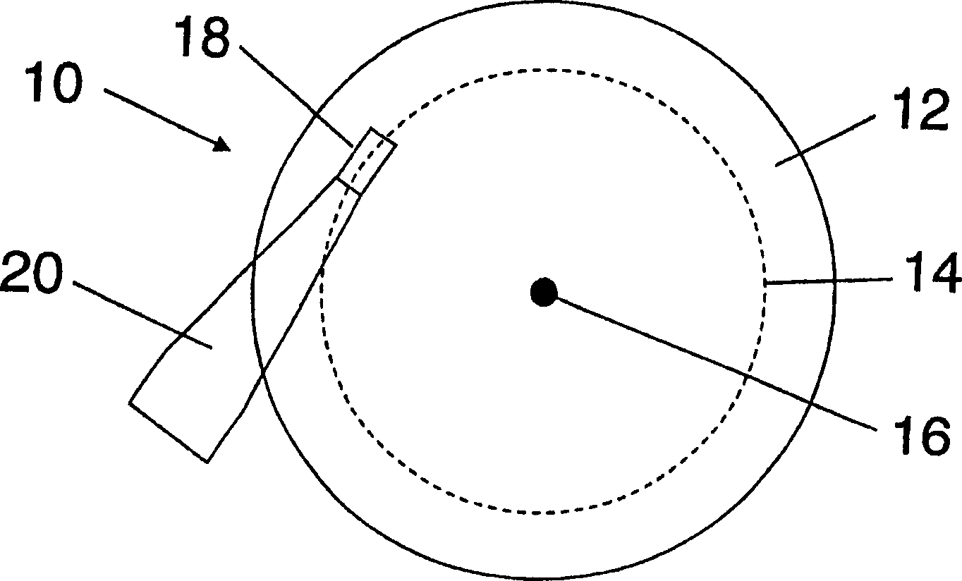
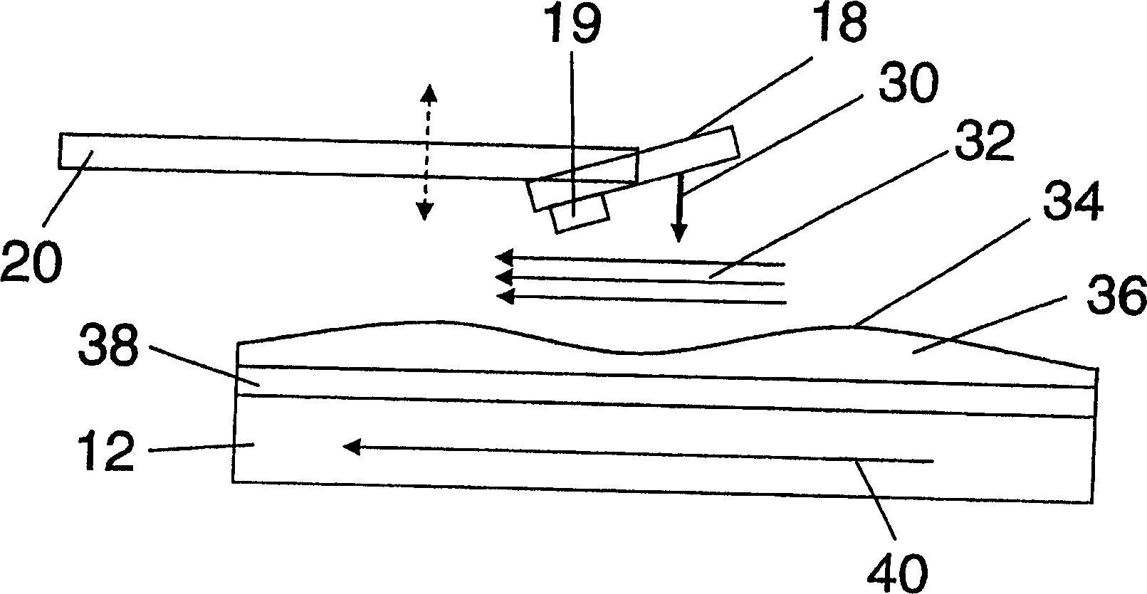
[0013] figure 1 A top view of a disk drive 10 is shown schematically. Disk drive 10 includes a disk 12 . One includes a read-write magnetic head 19 (such as image 3 shown, not in figure 1 upper) slider 18. Disk 12 rotates about axis 16 and has a layer 38 of magnetic recording material (such as image 3 shown). In magnetic recording material are multiple radially spaced tracks, one of which is figure 1 Expressed as 14 in. Slider bar 18 is positioned on track 14 such that magnetic head 19 is enabled to read data from or write data to track 14 . The slider 18 is a part of the magnetic head device 20 . The magnetic head device 20 includes (not in figure 1 appears in ) is used to position the head 19 at the desired radial position relative to the disk (ie, on the centerline of the selected disk).

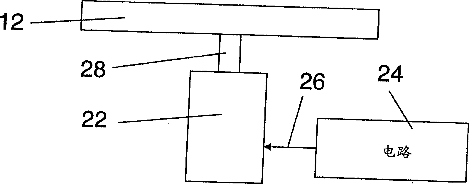
[0014] figure 2 outlines the figure 1 Side view of a disk drive in . A motor 22 is coupled to the disk 12 via a shaft 28 . A circuit 24 is controllably connected to the m...


PUM

PropertyMeasurementUnit
thicknessaaaaaaaaaa

Abstract

A disk drive having a layer of lubricant on the surface of the disk in which unwanted thickness adjustments of the lubricant layer are reduced by changing the ω / f of the disk drive during operation. Here ω is the angular velocity of the magnetic disk, and f is the resonance frequency of the magnetic head device accommodating the magnetic head. In this way, the magnitude of lubricant thickness adjustments is reduced, improving disk drive performance. The ratio ω / f is preferably changed by changing the angular velocity ω of the disk.

Description

technical field [0001] The present invention relates to disk drives, particularly disk drives having a lubricating layer between the surface of the disk and the read / write head. Background technique [0002] Disk drives typically include a thin layer of lubricant applied to the surface of the recording disk to reduce undesirable interactions between the head and disk, such as friction and stiction. Usually the thickness of the lubricant layer is between 0.8nm and 16nm. But in some cases, this range will be between 0.6 and 20 nanometers. Usually the material of the lubricant layer is a perfluoropolyether (PFPE) lubricant. PFPE lubricants are copolymers with the following chemical structure: [0003] X-[(OCF 2 CF 2 ) m -(OCF 2 ) n ]-O-X [0004] where m / n=2 / 3 and X represents the endgroups of the polymer. By selecting these end groups, the material can be modified to change the adsorption, affinity, activity, etc. of the thin layer. For PFPEZ, Zdol, and Ztetraol, so...

Claims


Application Information

Patent Timeline
Patent Type & Authority Applications(China)
IPC IPC(8): G11B21/21G11B5/008G11B15/46G11B19/04G11B19/28G11B21/02G11B21/08G11B25/04
CPCG11B19/04G11B19/28G11B21/08
Inventor 布鲁诺·马乔恩戴青弗迪南德·亨德里克斯乌拉尔·V·纳亚克
Owner HITACHI GLOBAL STORAGE TECH NETHERLANDS BV
Why Eureka
Try Eureka