Reflector and light source apparatus having reflector

A reflective mirror and reflective surface technology, which is applied in the field of reflective mirrors, can solve problems such as reflection and inability to perform the function of reflective mirrors, and achieve efficient cooling

Active Publication Date: 2005-05-04
USHIO DENKI KK
View PDF1 Cites 2 Cited by
  • Summary
  • Abstract
  • Description
  • Claims
  • Application Information

AI Technical Summary

Problems solved by technology

When such a strain occurs, the light emitted from the lamp cannot be reflected in th

Method used


Image

  • Reflector and light source apparatus having reflector
  • Reflector and light source apparatus having reflector
  • Reflector and light source apparatus having reflector

Examples


Embodiment Construction

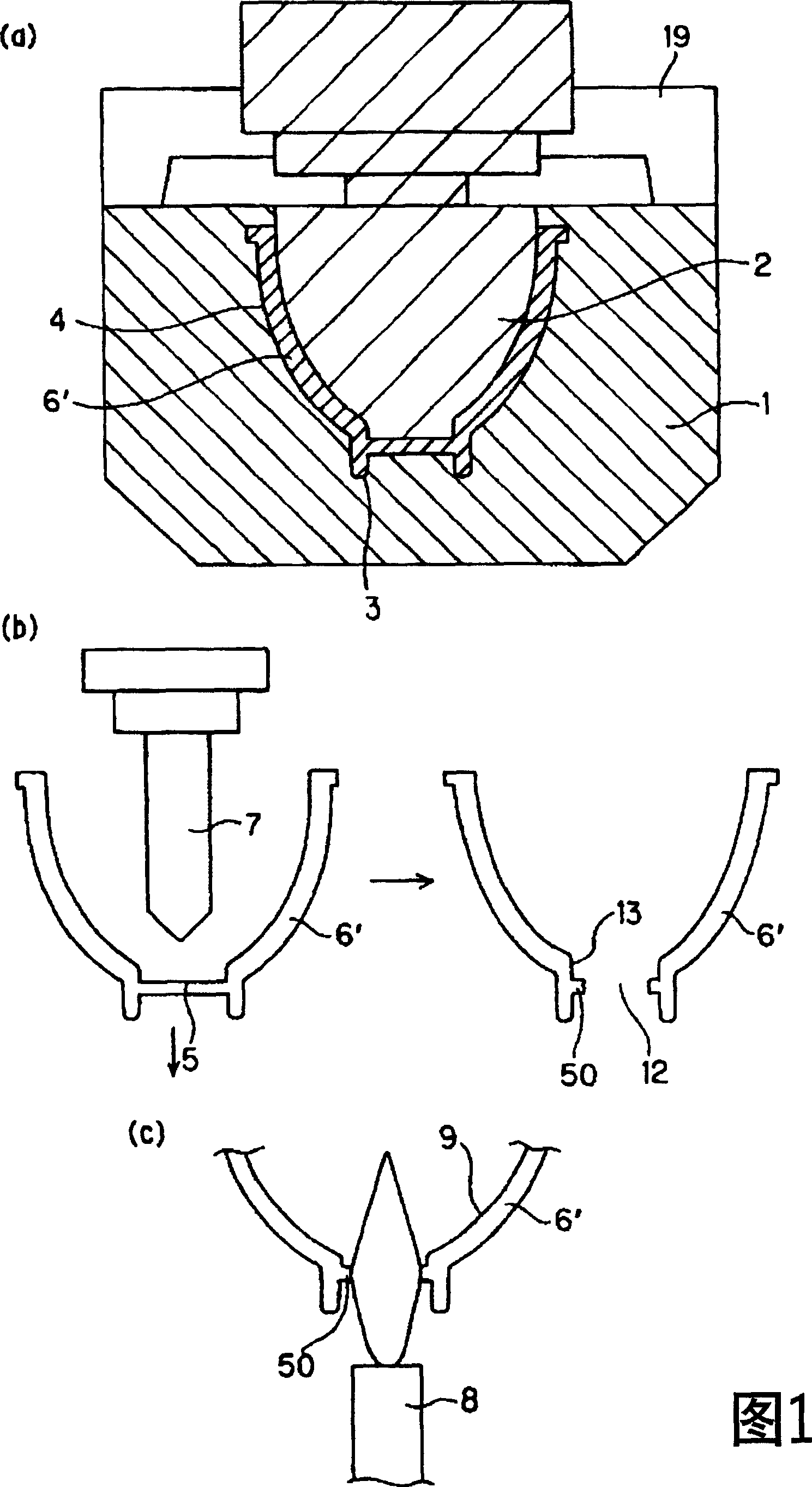
[0033] FIG. 1 is a diagram for explaining a method of manufacturing a reflecting mirror according to the present invention. As shown in FIG. 1 , the reflecting mirror according to the present invention is produced through the first to fourth steps.

[0034]

[0035] As shown in FIG. 1( a ), the female mold 1 has a concave portion suitable for the shape of the mirror to be molded, and has a neck hole 3 forming the neck of the mirror on the bottom of the concave portion. Molten borosilicate glass 4 is placed in the female mold 1, and press-fitted by applying pressure from above with a male mold. This male mold 2 is slightly smaller than the concave portion of the female mold 1, and forms the mold 6' of the reflecting mirror in the gap produced during pressing. The male die 2 is pushed down almost instantaneously, and the male die 2 is then raised. Then, the mold 6' of the reflecting mirror is taken out from the female mold 1 quickly after the male mold 2 is raised through th...


PUM

PropertyMeasurementUnit
Wall thicknessaaaaaaaaaa

Abstract

A reflector according to the present invention can certainly reflect light emitted from a lamp in a desired direction without producing distortion in a reflection surface by specifying the distance between a projection portion and a back side end portion of the reflection surface of a reflector to be in the optimal range. The reflector, having a front side opening portion, a back side opening portion and a reflection surface, the reflector comprises a projection portion provided in an inner surface of the reflector, wherein, the projection portion is formed in an area at a 2.5 mm or more distance from a back side end portion of the reflection surface toward a back side.

Description

technical field [0001] The present invention relates to a reflector made of borosilicate glass, and also to a light source device having an ultra-high pressure mercury lamp in the reflector. Background technique [0002] As light sources for liquid crystal projectors, there are known metal halide lamps that use halides of rare earth metals as luminescent substances, and mercury that is used as luminescent substances and that contain a large amount of mercury so that the mercury vapor pressure at the time of lighting becomes 150 atmospheres or more. ultra-high pressure mercury lamp. [0003] In recent years, such liquid crystal projector devices have been increasingly required to be smaller and lighter in order to be easily portable, and therefore, liquid crystal panels for liquid crystal projectors have been reduced in size year by year. Therefore, in order to efficiently condense light on a miniaturized liquid crystal panel, further miniaturization and higher brightness of...

Claims


Application Information

Patent Timeline
IPC IPC(8): F21S2/00F21V7/00F21V7/22F21V15/00F21Y101/00G03B15/02G03B21/28
CPCG03B21/28F21V7/22F21V7/28F21V7/24
Inventor 冈崎佳生
Owner USHIO DENKI KK
Why Eureka
Try Eureka