
Engineering machinery

A technology for construction machinery and cabs, which is applied in mechanical equipment, earthmoving machines/shovels, superstructure sub-assemblies, etc., and can solve problems such as danger to operators, inability to open doors, and inability for operators to escape from the vehicle. , to achieve the effect of protecting the cab, reducing manufacturing costs and ensuring safety

Inactive Publication Date: 2005-05-18
NIHON KENKI CO LTD
View PDF1 Cites 3 Cited by
  • Summary
  • Abstract
  • Description
  • Claims
  • Application Information

AI Technical Summary

Problems solved by technology

When such a cab is deformed due to direct impact, it will of course bring great danger to the operators who operate in the cab.
In addition, due to the deformation of such a cab, the door cannot be opened, and there is a danger that the operator cannot escape from the car.

Method used


Image

  • Engineering machinery
  • Engineering machinery
  • Engineering machinery

Examples


Embodiment Construction

[0022] Below, by using Figure 1-Figure 5 By showing how the invention may actually be practiced, the best form for carrying out the invention will be identified.

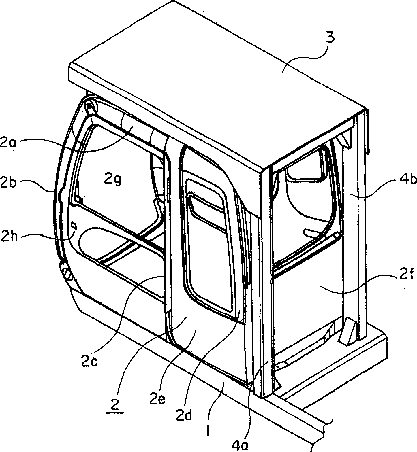
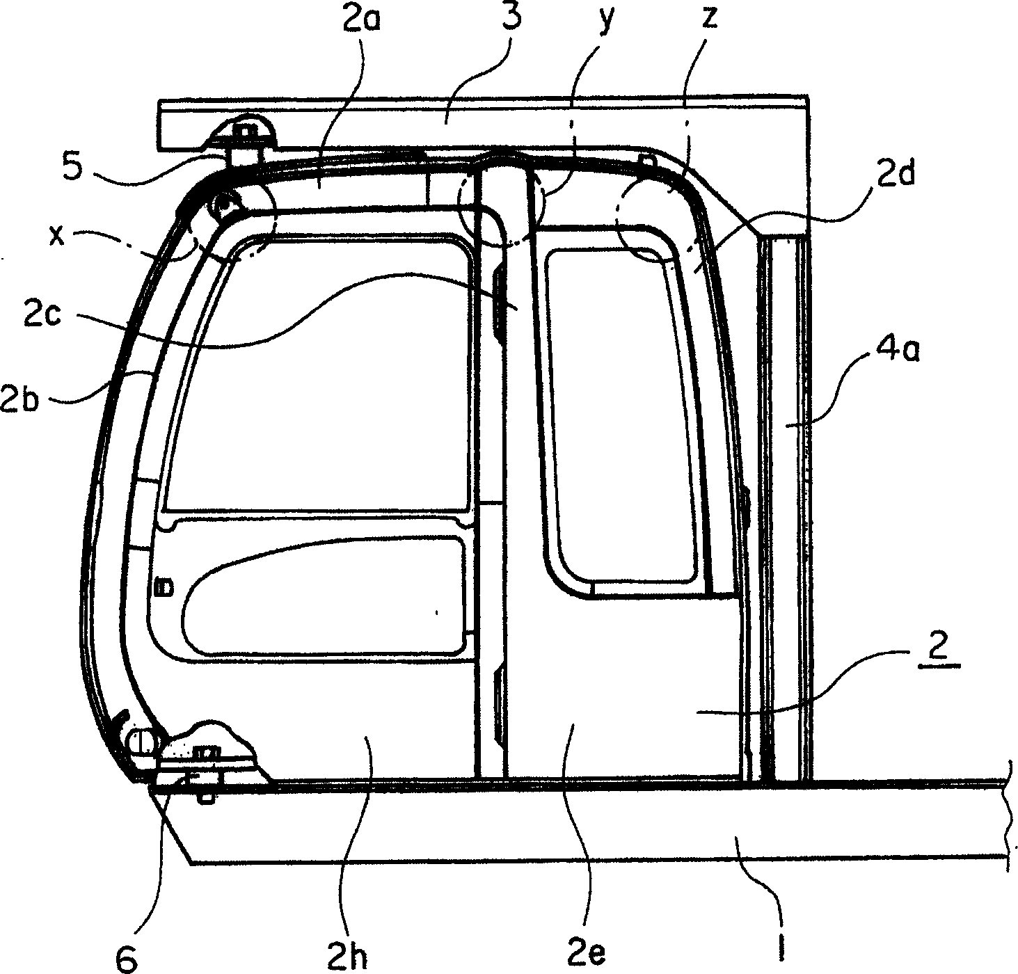
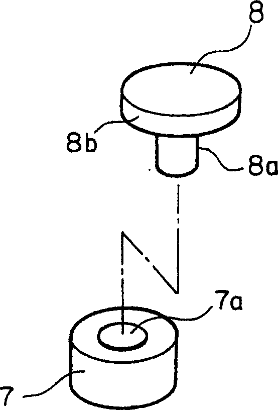
[0023] figure 1 It is a perspective view of a main part of a construction machine implementing a basic embodiment of the present invention. figure 1 It is a perspective view of a main part of a construction machine implementing a basic embodiment of the present invention. figure 2 yes figure 1 Side view of the main parts of construction machinery. image 3 It is an enlarged perspective view showing an example of a support device for a construction machine embodying the present invention. Figure 4 yes image 3 Vertical section view of the support device. Figure 5 It is an enlarged vertical cross-sectional view showing a second example of a construction machine support device embodying the present invention.

[0024] The following construction machines embodying the present invention are self-propelled cons...


PUM


Abstract

PROBLEM TO BE SOLVED: To provide a construction machine securing the safety of an operator in an operator's cabin by protecting the operator's cabin even if the construction machine turned over. SOLUTION: In this construction machine such as a hydraulic shovel having a swing frame 1 and the operator's cab installed on the swing frame 1, a protective structure 3 for the operator's cab for preventing the operator's cab 2 from receiving a direct impact when the construction machine is turned over is installed on the upper surface part 2a of the operator's cabin 2. The rear end part of the protective structure 3 for the operator's cabin is supported by a column 4a installed on the swing frame 1. A support body 5 supporting the front end part of the protective structure 3 for the operator's cab when the protective structure 3 for the operator's cab receives impact by the overturning of the construction machine is installed above the upper end part of a front pillar 2b between the upper surface part 2a of the operator's cabin 2 and the protective structure 3 for the operator's seat. COPYRIGHT: (C)2005,JPO&NCIPI

Description

technical field [0001] The present invention relates to a self-propelled construction machine such as a hydraulic excavator having a rotating frame and a cab provided on the rotating frame. Background technique [0002] A self-propelled construction machine such as a hydraulic excavator is composed of a lower traveling body and an upper rotating body. The lower traveling body uses crawler belts for the self-propelled construction machine to travel. The upper rotating body is rotatably provided on the lower traveling body. The upper rotating body is provided with devices such as a driver's cab, a mechanical room, and a counterweight on the rotating frame as its chassis. A working device (front end) is usually provided at the front end of the rotating frame. The working device has a beam that can tilt relative to the rotating frame, a forearm that can swing relative to the beam, and additional devices such as a bucket that can swing relative to the forearm to perform various o...

Claims


Application Information

Patent Timeline
IPC IPC(8): E02F9/16B60R21/11B62D25/06B62D25/08B62D33/06E02F9/24F16F7/00
CPCB60Y2200/41B62D33/06E02F9/0858E02F9/16E02F9/163
Inventor 小林敬弘田村和久
Owner NIHON KENKI CO LTD
Learn More