Fluid compressor

A technology of compressor and compression mechanism, which is applied in the field of air or other fluid compressors and refrigerant compressors, which can solve the problems of reducing the centrifugal effect, high price of volumetric pump parts, and inability to ensure oil supply, etc., and achieves low-cost structure, The effect of superior reliability

Inactive Publication Date: 2005-05-18
HITACHI JOHNSON CONTROLS AIR CONDITIONING INC
View PDF2 Cites 4 Cited by
  • Summary
  • Abstract
  • Description
  • Claims
  • Application Information

AI Technical Summary

Problems solved by technology

However, there is a problem that the price of the positive displacement pump part is generally higher than that of the centrifugal pump part
[0008] The screw compressor shown in Japanese Unexamined Patent Publication No. 2-245492 has an inexpensive structure because a centrifugal pump unit is used, but the second oil passage is connected within the plane of the first oil passage, and there is only one second oil passage , thus having the problem of ensuring adequate oil supply
In addition, since the viscosity of the oil decreases when the oil temperature rises, the centrifugal effect acting on the inner wall is reduced in the centrifugal pump part, and there is a problem that the necessary oil supply cannot be ensured.

Method used


Image

  • Fluid compressor
  • Fluid compressor
  • Fluid compressor

Examples


Embodiment Construction

[0024] Hereinafter, several embodiments of the present invention will be described with reference to the drawings. The same symbols in the drawings of the respective embodiments represent the same objects or members corresponding to the objects.

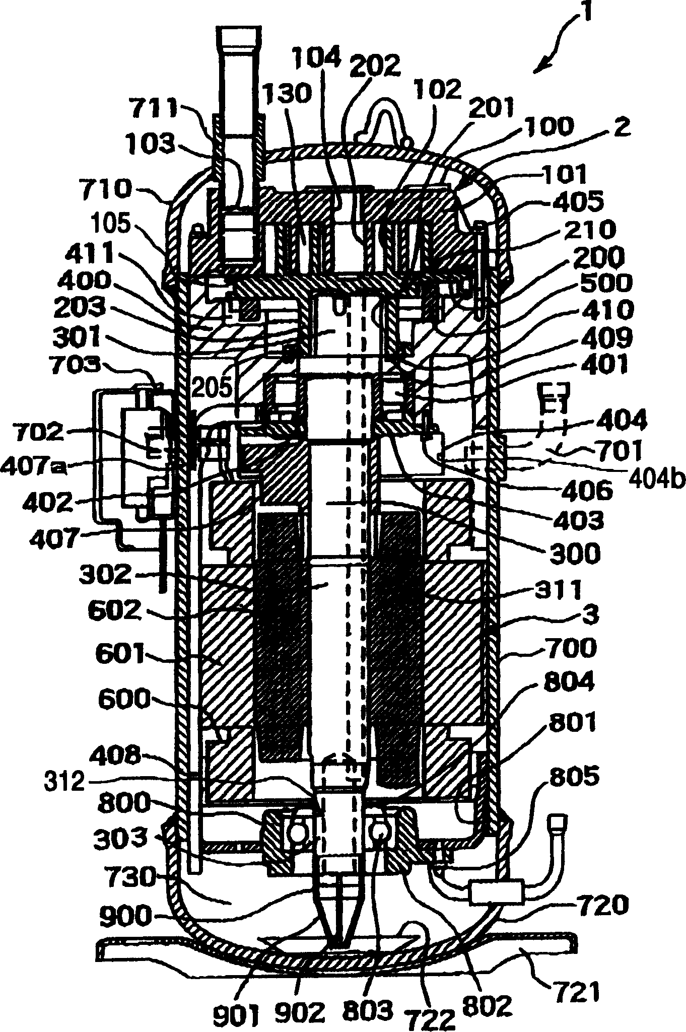
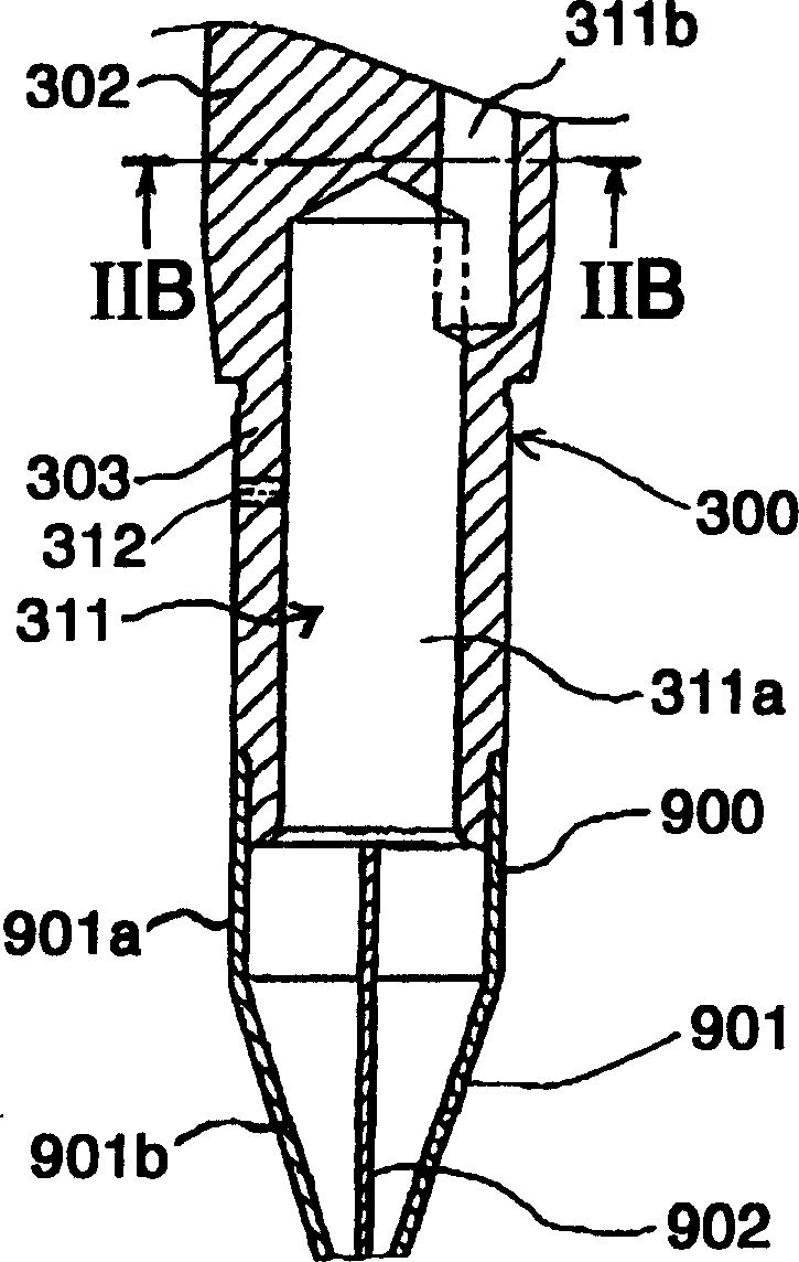
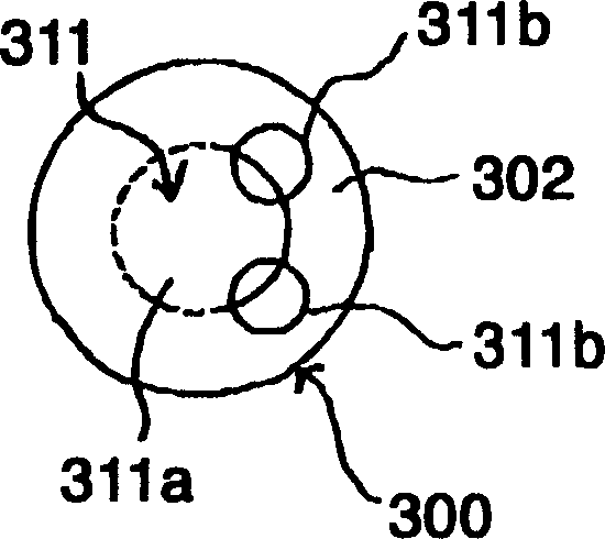
[0025] refer to figure 1 , Figure 2A and Figure 2B , the scroll compressor according to the first embodiment of the present invention will be described. figure 1 is a longitudinal sectional view of a scroll compressor according to a first embodiment of the present invention, Figure 2A yes figure 1 A longitudinal sectional view of the lower part of the rotating shaft and the pump part of the scroll compressor, Figure 2B yes Figure 2A The IIB-IIB sectional view.

[0026] The scroll compressor 1 has a structure in which the compression mechanism unit 2 and the drive unit 3 are accommodated in a sealed container 700 . In this embodiment, the compression mechanism unit 2 , the drive unit 3 , and the oil tank 703 are arranged ...


PUM


Abstract

A fluid compressor, a fluid compressor (1), comprising: a rotating shaft (300) having a compression mechanism (2) and an oil passage (311), an electric motor (600), bearings (401, 803), and an oil passage (311) Centrifugal pump section (900) for oil supply. The rotating shaft (300) has a main shaft part (302), a crank pin (301) eccentrically arranged on the main shaft part (302), and an auxiliary bearing support part (303) smaller in diameter than the main shaft part (302). The oil passage (311) has a first oil passage (311a) extending from the lower end of the auxiliary bearing support part (303) to the lower part of the main shaft part (302), and communicates with the first oil passage (311a) and extends to the crank The second oil passage (311b) at the upper end of the pin (301). The second oil passage (311b) has a diameter smaller than that of the first oil passage (311a), has an outer passage portion, and is formed in plural within the plane range of the crank pin (301).

Description

technical field [0001] The present invention relates to a fluid compressor including a rotating shaft with an oil passage, in particular to a refrigerant compressor for refrigeration, air conditioning, air or other fluid compressors. Background technique [0002] A conventional fluid compressor is shown in JP-A-2001-349291. of JP-A-2001-349291 figure 1 The screw compressor above has in its airtight container: a compression mechanism part for compressing fluid, a rotating shaft connected to the compression mechanism part and having an oil passage, a motor driving the rotating shaft, and a main shaft supporting the rotating shaft above the motor. Bearings, sub-bearings that support the rotating shaft under the motor, and positive displacement pumps that supply oil stored in the bottom of the airtight container to the compression mechanism and bearings through the oil passage. [0003] And, the rotating shaft has, as a whole, a main shaft part fixed on the motor rotor, a cran...

Claims


Application Information

Patent Timeline
Patent Type & Authority Applications(China)
IPC IPC(8): F04B17/00F04B35/04F04B39/02F04C18/02F04C23/00F04C29/02
CPCF04B39/0253F04C18/0215F04C23/008F04C29/023F04C29/025F04B39/02F04C18/02
Inventor 太田原优野泽重和松永睦宪中村聪长谷川修士土屋豪柳濑裕一安则俊典除补义信
Owner HITACHI JOHNSON CONTROLS AIR CONDITIONING INC
Why Eureka
Try Eureka