Rotary machine with rotary sensor

A technology of rotating machines, rotating detectors, applied in the direction of instruments, devices using electrical/magnetic methods, control/regulatory systems, etc.

Inactive Publication Date: 2005-05-18
ASMO CO LTD
View PDF1 Cites 31 Cited by
  • Summary
  • Abstract
  • Description
  • Claims
  • Application Information

AI Technical Summary

Problems solved by technology

Since the rotation detection error due to the deformation of the encoder disk 204 is in the form of a sine wave with a change of two periods per rotation of the rotary shaft 202, it cannot be eliminated by the above-mentioned conventional technology.

Method used


Image

  • Rotary machine with rotary sensor
  • Rotary machine with rotary sensor
  • Rotary machine with rotary sensor

Examples


Embodiment Construction

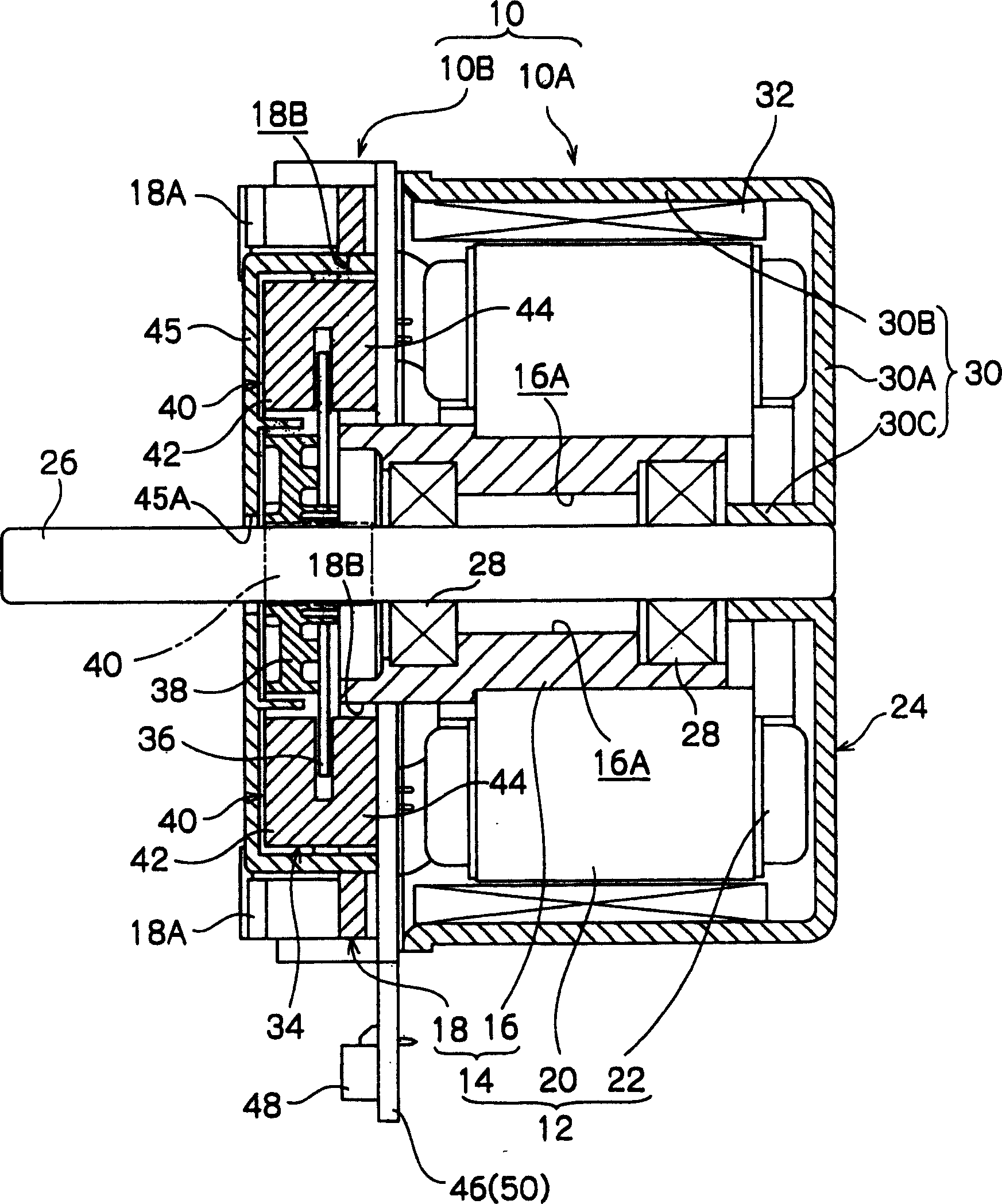
[0029] according to figure 1 Referring to FIG. 8 , an electric motor (rotary machine) according to an embodiment of the present invention, that is, an outer rotor type motor 10 will be described. First, the overall schematic configuration of the motor unit 10A of the outer rotor type motor 10 will be described, and then the rotation control unit 10B as the rotation control device, which is the main part of the present invention, will be described.

[0030] exist figure 1 In , a side section of the outer rotor type motor 10 is shown. As shown in the figure, the outer rotor type motor 10 is composed of a motor unit 10A and a rotation control unit 10B which will be described later. The motor unit 10A includes a stator 12 , and the stator 12 includes a stator base 14 . The stator base 14 is composed of a substantially cylindrical central tube portion 16 and a flat plate-shaped stator cover 18 protruding from an outer peripheral portion of one end portion of the central tube p...


PUM


Abstract

The present invention provides a rotary machine. Three rotation sensors arranged at intervals of 90 degrees in the circumferential direction of a disc-shaped code wheel mounted on an output shaft of a motor output signals corresponding to the rotational speed of the code wheel, respectively. If the code disc is eccentric with respect to the output shaft, an error component (1 cycle component) will be generated when it is rotated for one cycle, and if it is deformed into an ellipse, an error component will be changed for two cycles ( 2 cycle components). The control device averages the output signal of the first rotation sensor and the output signal of the second rotation sensor to eliminate the first correction signal of the two-cycle component, and the output signal of the first rotation sensor and the output of the third rotation sensor The second correction signal from which the 2-period component is eliminated based on the signal difference is added or subtracted by matching the phase and amplitude of the remaining 1-period component to calculate the rotation detection signal from which the 1-period component and the 2-period component have been eliminated.

Description

technical field [0001] The present invention relates to a rotating machine capable of controlling the rotational speed or the rotational angle of a rotating shaft or a rotating body connected to the rotating shaft. Background technique [0002] For example, image processing devices (image forming devices) such as color copiers and color printers are equipped with four-color (black, yellow, blue, red) photosensitive drums, and these photosensitive drums are rotated at low speed by electric motors as rotating machines ( 40rpm to 100rpm). In the motor for rotationally driving the photosensitive drum, it is desired that the problem of non-uniformity of rotation that deteriorates the image does not occur during the above-mentioned low-speed rotation. [0003] Therefore, an encoder is provided to detect the rotation speed of the rotation shaft of the motor or the coupling shaft of the photosensitive drum coupled to the rotation shaft, and the rotation speed of the photosensitive ...

Claims


Application Information

Patent Timeline
Patent Type & Authority Applications(China)
IPC IPC(8): G01P3/44G05D13/00
Inventor 内山治彦夏目英彦
Owner ASMO CO LTD
Why Eureka
Try Eureka