Self light emission display device

A display device and a self-illuminating technology, which can be applied to identification devices, lighting devices, electroluminescent light sources, etc., and can solve problems such as cost problems and physical limitations of data driver configuration structures.

Inactive Publication Date: 2005-05-18
TOHOKU PIONEER CORP
View PDF1 Cites 5 Cited by
  • Summary
  • Abstract
  • Description
  • Claims
  • Application Information

AI Technical Summary

Problems solved by technology

[0016] As mentioned above, although the dual-scanning driving method can prolong the light-emitting working time of the element, it needs to be equipped with two independent data drivers, and there is a cost problem.
In addition, even if it is possible to increase the size of the display screen by bonding the display panels together, there are still physical limitations in terms of the arrangement structure of the data driver.

Method used


Image

  • Self light emission display device
  • Self light emission display device
  • Self light emission display device

Examples


Embodiment Construction

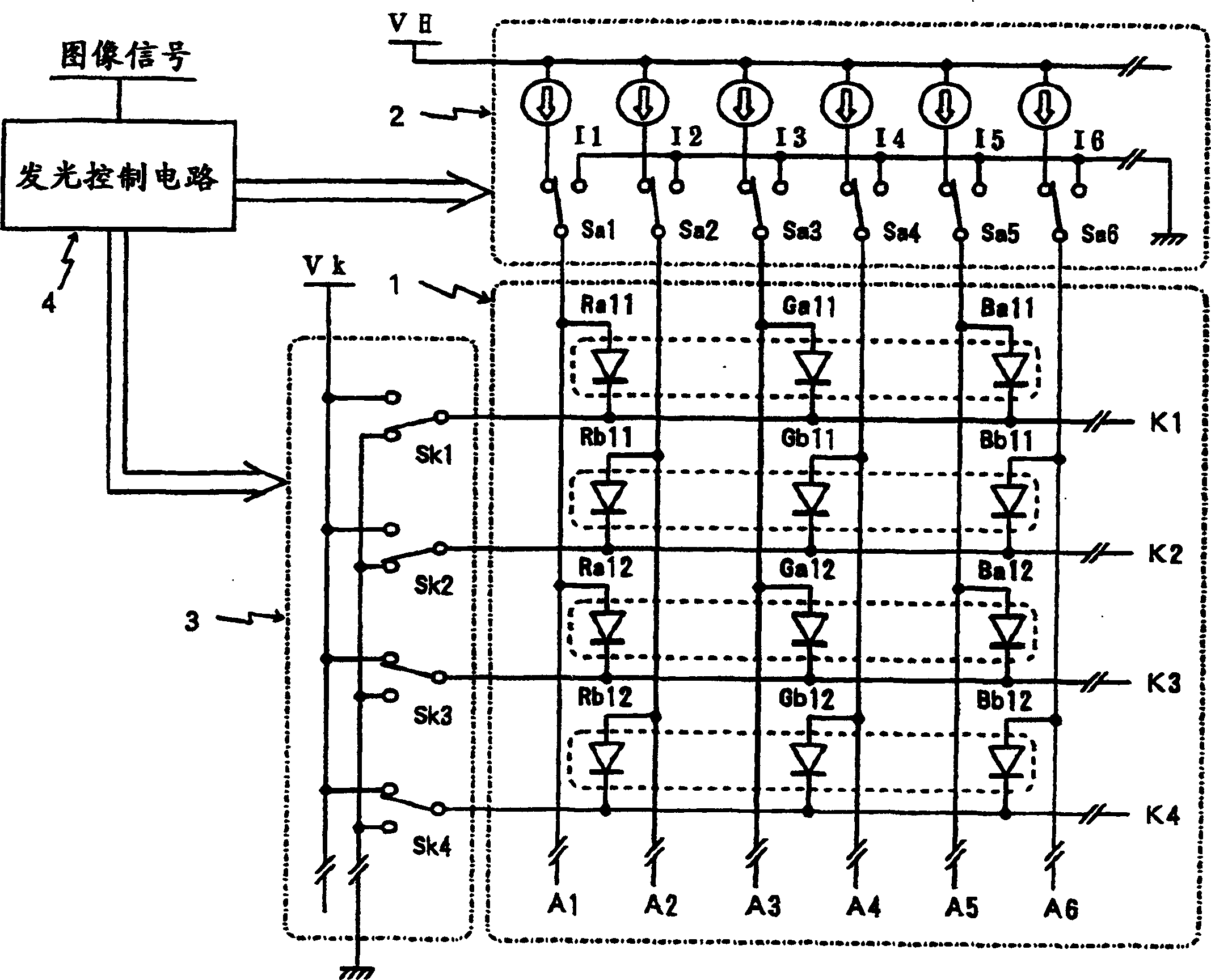
[0029] Below, based on image 3 and Figure 4 The illustrated embodiments illustrate self-luminous display devices of the invention. first, image 3 Represents the structure of the passive matrix display panel and its drive circuit of the present invention, the image 3 The shown display panel 1 adopts the method of cathode line scanning / anode line driving. In the figure, as surrounded by a dotted line, a group of three sub-pixels that emit light in each color of R (red), G (green), and B (blue) forms a structure of one pixel (pixel).

[0030] image 3 In the shown display panel 1 , anode lines serving as data lines are arranged along the column (vertical) direction, and cathode lines serving as scanning lines are arranged along the row (horizontal) direction. And, among the two adjacent anode lines, for example, among the anode lines A1 and A2, one of the anode lines A1 is connected to the anode terminal of the red light-emitting EL element Ra11 indicated by the mark of ...


PUM


Abstract

The present invention provides a self-luminous display device capable of substantially double-scanning driving by one data driver, wherein: a plurality of scanning lines ( K1 , K2 . . . ) A plurality of data lines (A1, A2...), and a plurality of light-emitting elements (Ra11, Rb11...) arranged in intersection regions of the scan lines and data lines. The anode terminals thereof are respectively connected to the cathode terminals of the light-emitting elements of the two adjacent data lines A1 and A2, and are sequentially connected to different scanning lines. Moreover, any two of the scanning lines are scanned and selected at the same time. Accordingly, the light emission operation time of each EL element can be approximately doubled, so that the instantaneous light emission luminance of each EL element can be set to a low value, and the workload on the EL element can be reduced. In addition, since each data line can be drawn out at one end of the display panel, it is possible to substantially perform double-scanning driving with one data driver.

Description

technical field [0001] The present invention relates to a self-luminous display device for a passive matrix type display panel using a light-emitting element such as an organic EL (electroluminescent) element, and particularly relates to a self-luminous display device suitable for forming a large-sized display panel. Background technique [0002] The development of a display panel formed by arranging light emitting elements in a matrix is ​​being widely advanced, and as a light emitting element used in such a display panel, an organic EL element in which a light emitting layer is made of an organic material has attracted attention. This is based on the background that by using an organic compound expected to have good light-emitting characteristics in the light-emitting layer of the device, progress has been made in improving efficiency and extending life that meet practical requirements. [0003] The above-mentioned organic EL element can be electrically replaced with a lig...

Claims


Application Information

Patent Timeline
Patent Type & Authority Applications(China)
IPC IPC(8): H01L51/50G09F9/30G09G3/20G09G3/30G09G3/32H01L27/32H05B33/14
CPCG09G3/3216G09G3/3266G09G3/3275G09G2300/0426G09G2300/0439G09G2310/0205G09G2310/0221H10K59/17G09G3/30G09G3/20
Inventor 关修一
Owner TOHOKU PIONEER CORP
Why Eureka
Try Eureka