Shaft damper

A technology for dampers and damping shafts, applied in the direction of shafts, flexible shafts, shock absorbers, etc., can solve problems such as no effect of bending vibration

Inactive Publication Date: 2005-05-25
THE GATES CORP
View PDF1 Cites 11 Cited by
  • Summary
  • Abstract
  • Description
  • Claims
  • Application Information

AI Technical Summary

Problems solved by technology

These techniques present problems with respect to operating space and damping coefficients
Also, they are primarily used for torsional damping and are ineffective for damping bending vibrations along the length of the shaft

Method used


Image

  • Shaft damper
  • Shaft damper
  • Shaft damper

Examples


Embodiment Construction

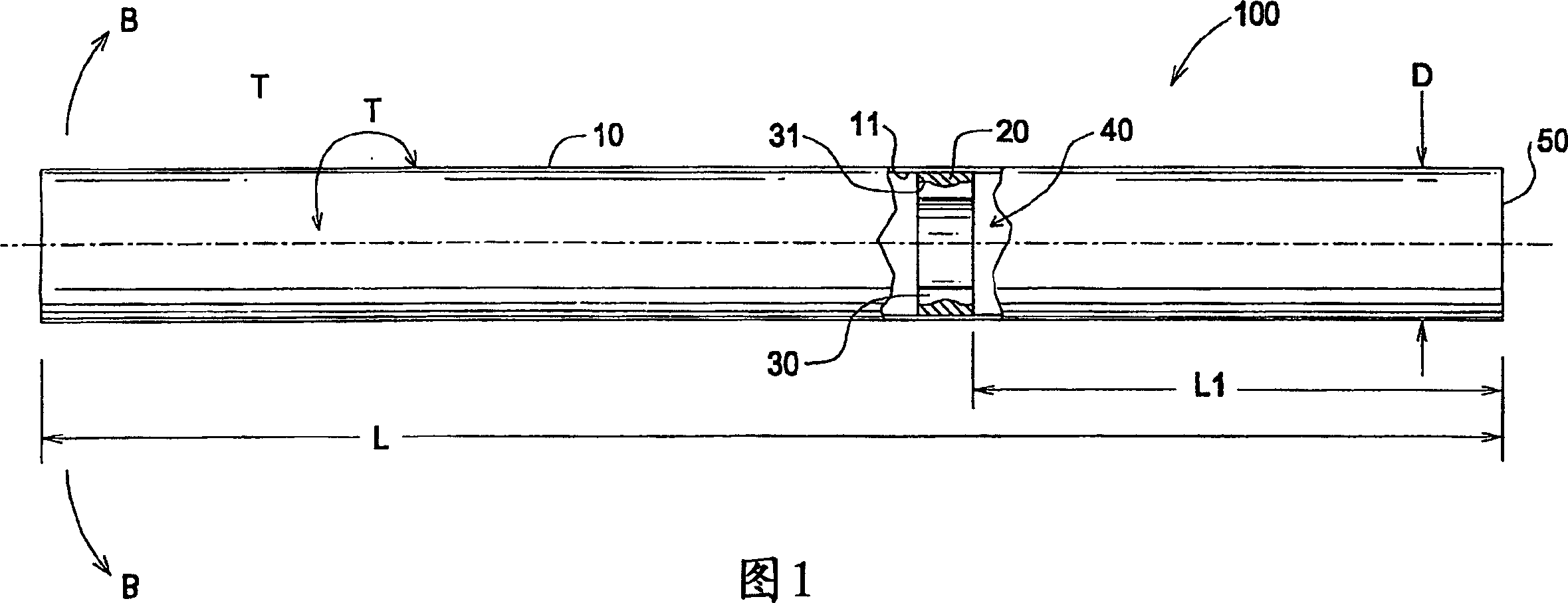
[0015] Figure 1 is a cross-sectional side view of the shaft damper of the present invention. The shaft damper 100 includes a shaft body 10 and a hole 40 . The shaft 10 has a length L and a diameter D. The elastic member 20 is engaged between the shaft body 10 and the inertia member 30 in the hole 40 . The elastic member 20 and the inertial member 30 are located at a distance L1 from the end 50 of the shaft 10 .

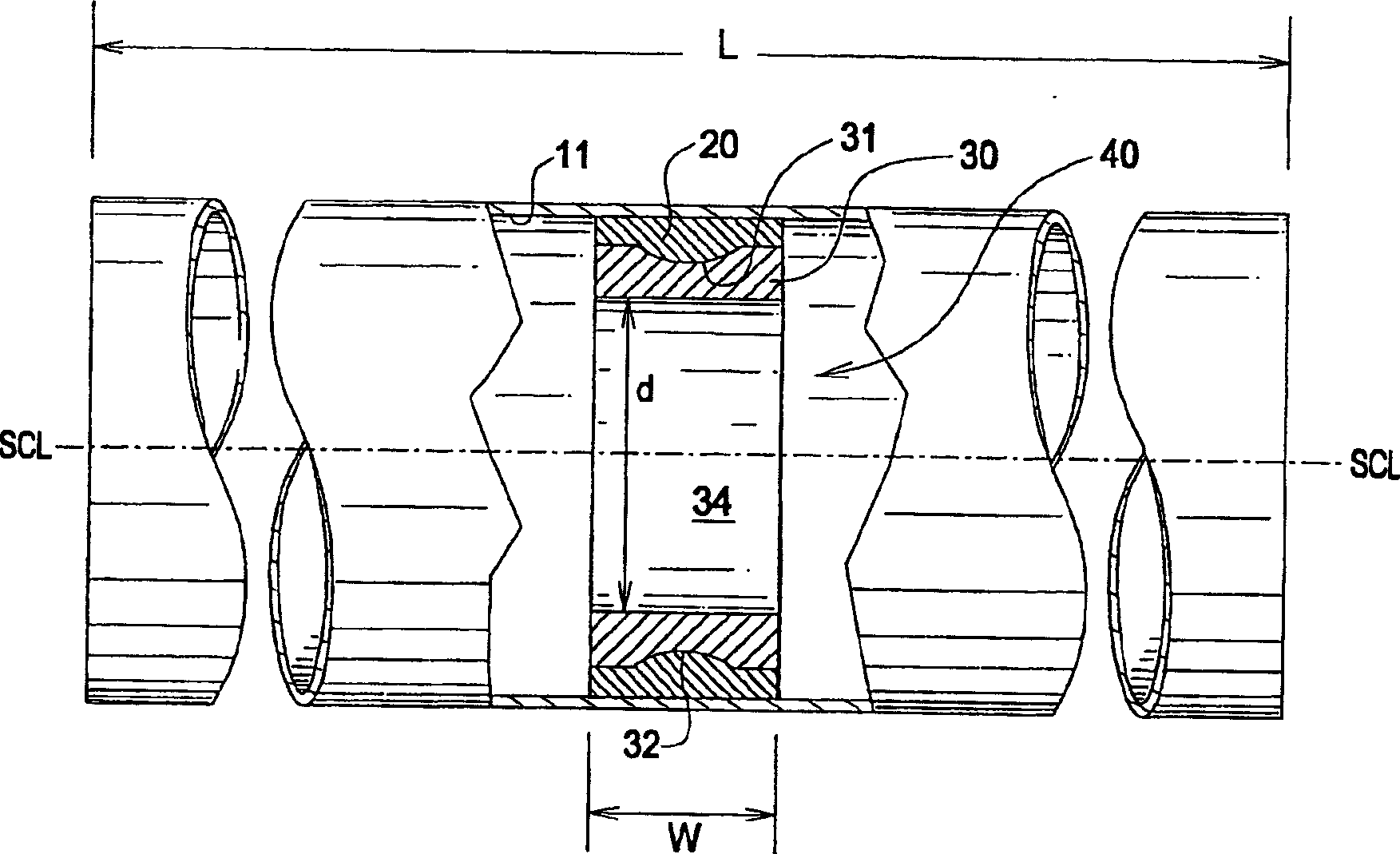
[0016] figure 2 is a detailed view of the shaft damper of the present invention. The elastic member 20 is engaged between the inner surface 11 of the shaft and the outer surface 31 of the inertia member. The inner surface 11 may have a surface roughening to increase the surface coefficient of friction.

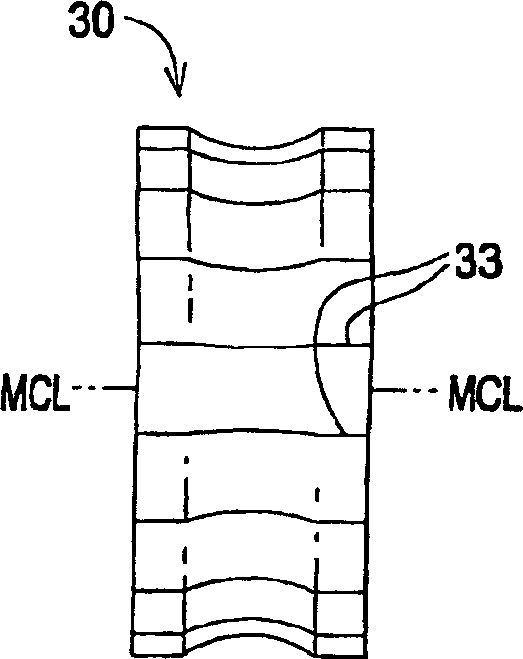
[0017] The elastic member 20 is compressed between the inner surface 11 and the outer surface 31 in the range of 5% to 50%. The inertial member 30 further includes an undulating surface 32 on the outer surface 31 for mechanically engaging the inertial member 30 ...


PUM


Abstract

The invention includes a shaft damper (100) having an inertial member (30) engaged with a resilient member (20) within a shaft bore (40). The elastic member is contained in the annular space between the inner surface (11) of the shaft and the outer surface (31) of the inertia member, the outer surface of the inertia member being configured to enhance the mechanical connection with the elastic member. The elastic member and the inertial member are arranged in the shaft to damp the bending vibration of the shaft.

Description

technical field [0001] The invention relates to a shaft damper, in particular to a shaft damper comprising an elastic part and an inertia part at a predetermined position in a shaft hole. Background technique [0002] Rotating shafts typically vibrate in various ways depending on the type of equipment. Shaft vibration produces noise. Dampers are known to damp shaft vibrations. The damper reduces operating noise and premature wear of the shaft and failure of the shaft due to fatigue. [0003] The damper may take the form of a deformable pad within the drive shaft. A torsional damper may also be included comprising an inertial member secured within an annular cavity on the outer surface of the shaft. [0004] Representative of this technology is US Patent No. 5,749,269 (1998) to Szymanski et al., which discloses a viscous torsional vibration damper having an annular cavity surrounding an axis within which the inertial member is contained. [0005] The representative of th...

Claims


Application Information

Patent Timeline
Patent Type & Authority Applications(China)
IPC IPC(8): F16F15/14
CPCF16F15/1442F16F15/10F16C1/00
Inventor 朱霖瓦亚·霍德雅特马克·R·卡达雷特
Owner THE GATES CORP
Why Eureka
Try Eureka