
Floor sweeping machine

A technology for sweeping machines and operating levers, which is applied in the direction of cleaning carpets, cleaning floors, floor leveling/polishing machines, etc. It can solve the problems of dust collection, collection and removal of dust, etc., and achieve the effect of solving the problem of dust.

Active Publication Date: 2005-06-01
NINGBO TROIKA SCI
View PDF1 Cites 21 Cited by
  • Summary
  • Abstract
  • Description
  • Claims
  • Application Information

AI Technical Summary

Problems solved by technology

This kind of sweeper has the functions of collecting, collecting and removing dust, and has the characteristics of simple structure, low cost, direct current as the power source, and convenient use. The function may not be satisfactory

Method used


Image

  • Floor sweeping machine
  • Floor sweeping machine
  • Floor sweeping machine

Examples


Embodiment Construction

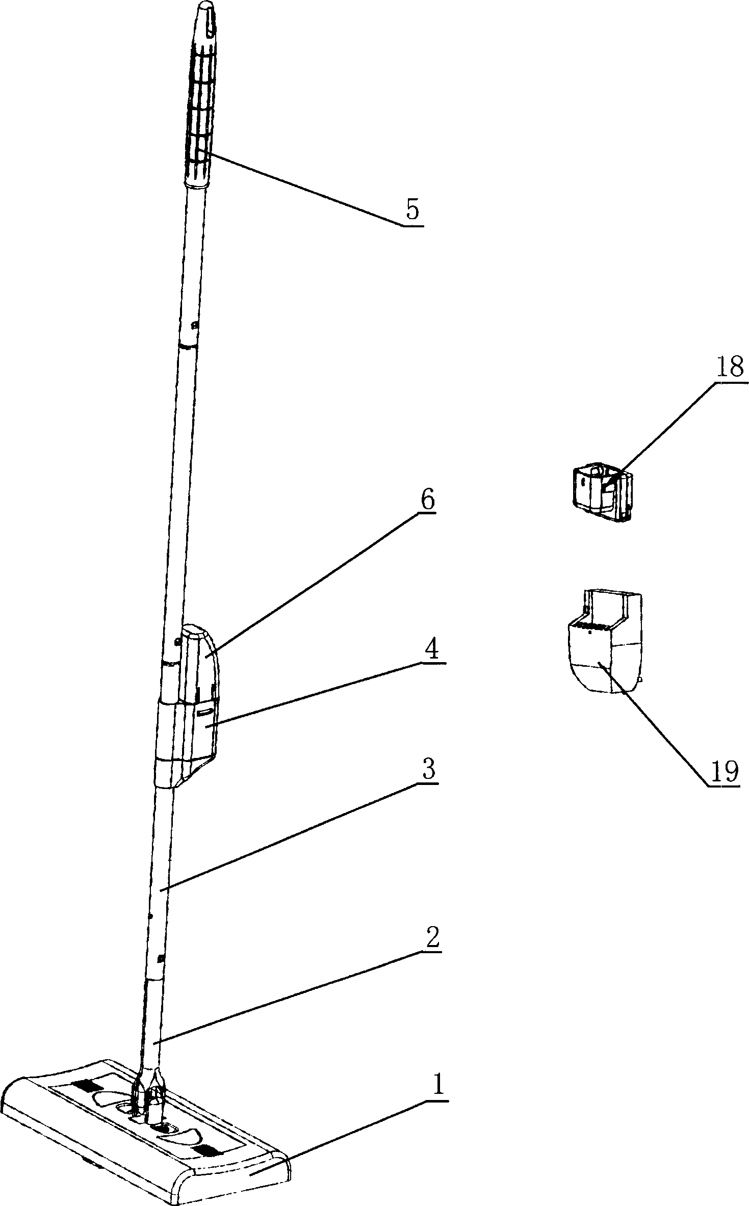
[0017] The following is attached Figure 1-4 To illustrate the structure of the present invention.

[0018] Sweeping machine structure of the present invention such as figure 1 As shown, it includes ground brush (1), universal joint (2), operating lever (3), battery holder (4), handle (5) and battery (6), etc.

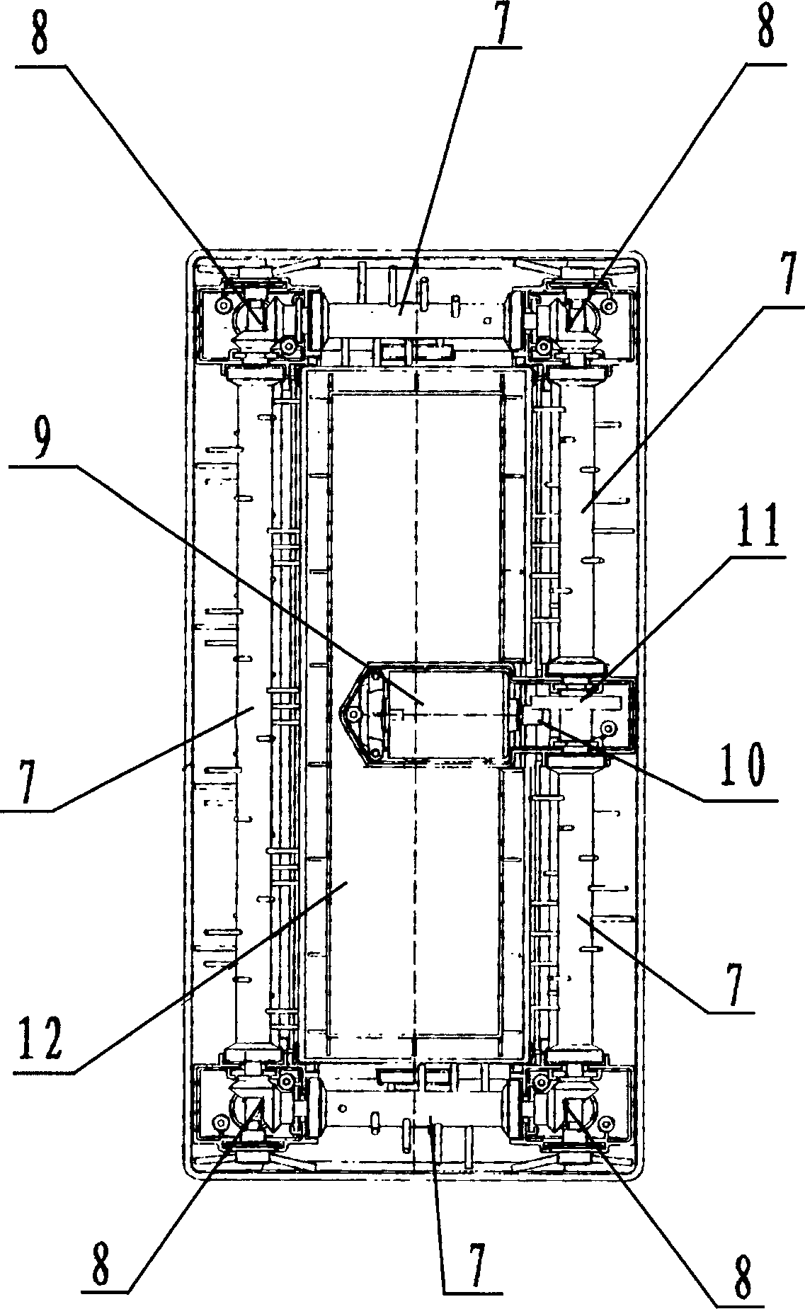
[0019] As shown in figure (2), in the bottom of the ground brush (1), a rotatable hairbrush (7) is installed on the inner side around, and the two ends of the shaft of the hairbrush (7) have helical gear seats (8). Through helical gear seat (8) interconnect transmission; At the bottom inner middle part of ground brush (1), be provided with micromotor (9), the gear (10) of motor (9) is connected transmission with hairbrush shaft gear (11).

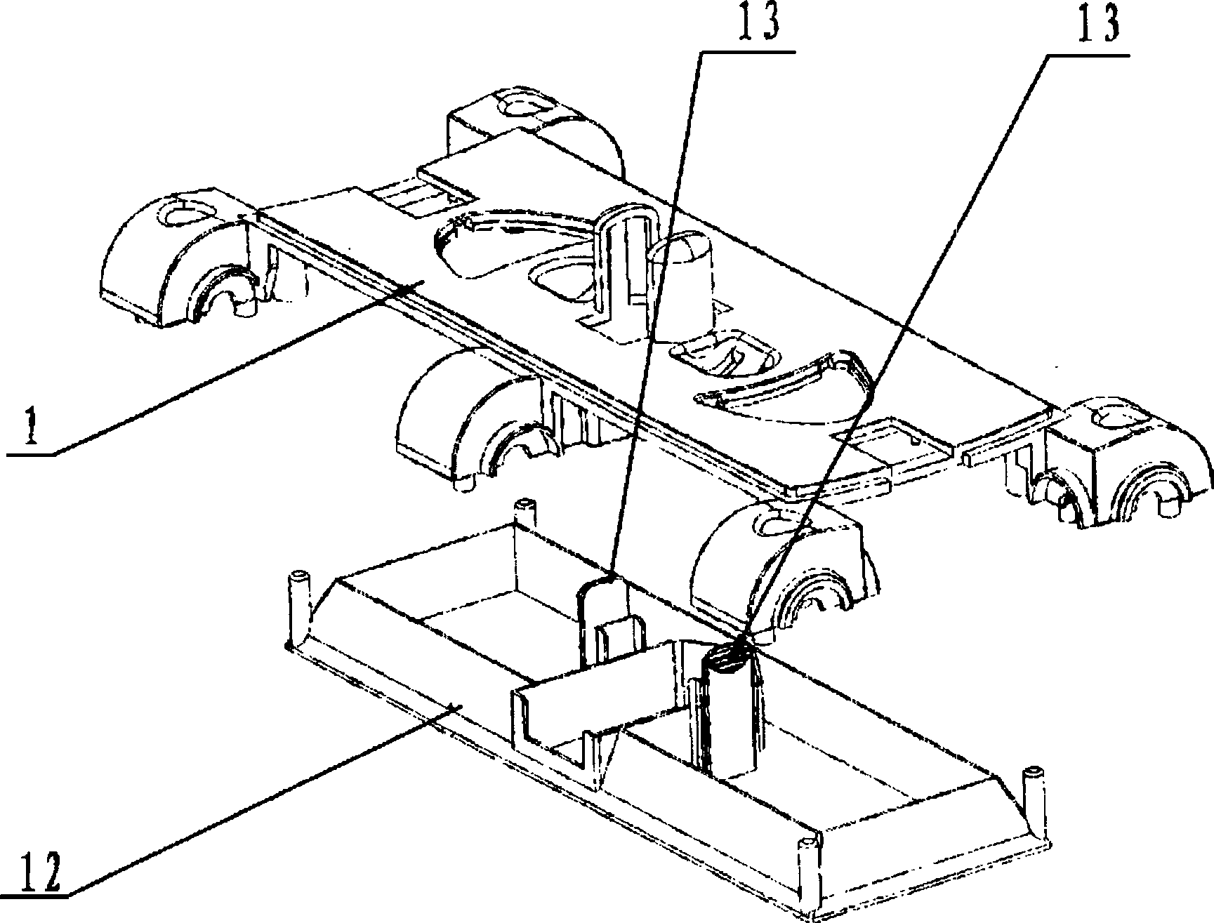
[0020] Such as image 3 As shown, in the middle part of the bottom of the ground brush (1), a dust collection bin (12) is provided, and the dust collection bin (12) is fixed by a deck (13) arranged on the ground brush (1) structu...


PUM


Abstract

The floor sweeping machine includes floor brush, universal joint, operating rod, battery seat, handle, brush and dust collecting bin. The floor brush is connected via the universal joint tot rod, and has rotary brushes installed to the peripheral of its bottom and connected via bevel gear seats on two ends for rotation and dust collecting bin set in the middle of its bottom. The brushes rotate from outside to inside to collect the dust on floor to the middle dust collecting bin without flying, and the dust collecting bin is easy to take off for cleaning before reuse.

Description

1. Technical field [0001] The present invention relates to a cleaning machine, more particularly to a domestic sweeping machine capable of effectively removing dust and dirt. 2. Background technology [0002] Ordinary household sweepers, in the process of cleaning the ground environment of the home, there will always be some dust flying up, and the dust cannot be completely cleaned. When the existing household vacuum cleaners clean the home environment, there are always some dead corners that cannot be cleaned, such as under the cabinet bottom of the wardrobe. Dead ends cannot be removed. [0003] In the Chinese patent CN-2527216, a sweeping machine is disclosed. The front end of the body is provided with a brush chamber, and the brush chamber is provided with a brush rod with bristles. There is an ash collecting baffle, the brush room on the top of the ash collecting baffle is connected with the ash collecting room, the ash collecting bucket is located at the rear end of ...

Claims


Application Information

Patent Timeline
IPC IPC(8): A47L11/00A47L11/18
Inventor 田吉传俞建福金时波
Owner NINGBO TROIKA SCI
Learn More