

Liquid leakage detector
A detector and liquid leakage technology, which is applied in the direction of detecting the appearance of fluid at the leakage point, using liquid/vacuum degree to measure the liquid tightness, and using electrical devices to test the fluid tightness, etc., can solve the problem of costing man-hours for installation , to achieve the effect of reducing installation man-hours and realizing costs
- Summary
- Abstract
- Description
- Claims
- Application Information
AI Technical Summary
Problems solved by technology
Method used
Image

Examples
Embodiment 1
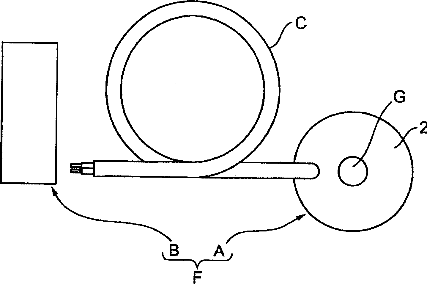
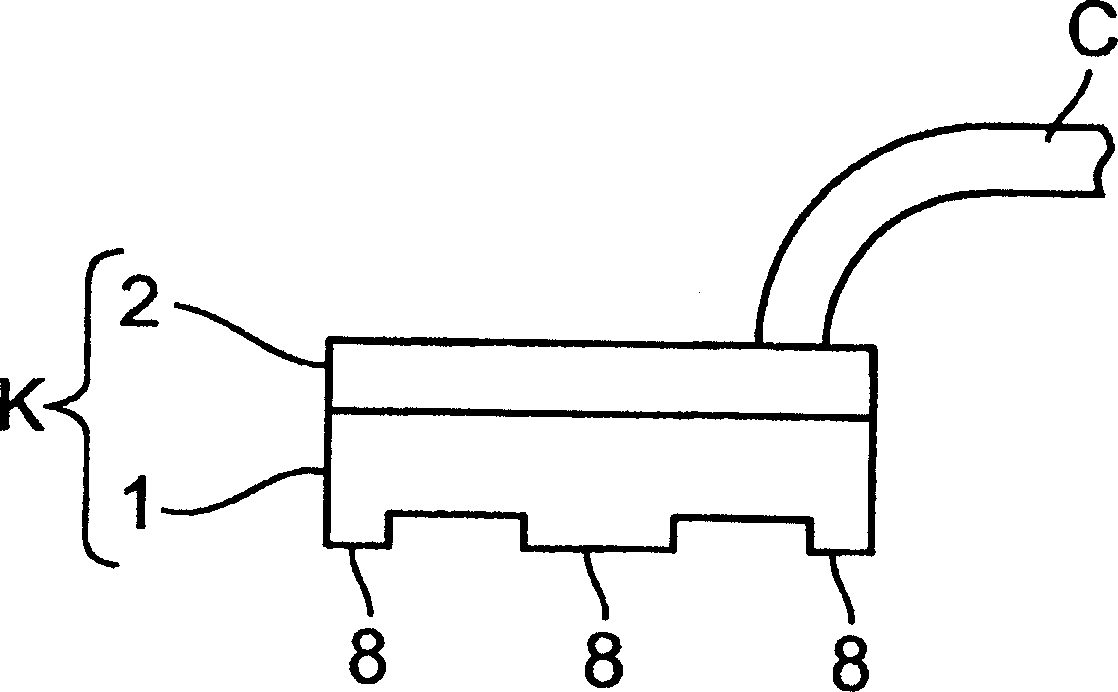
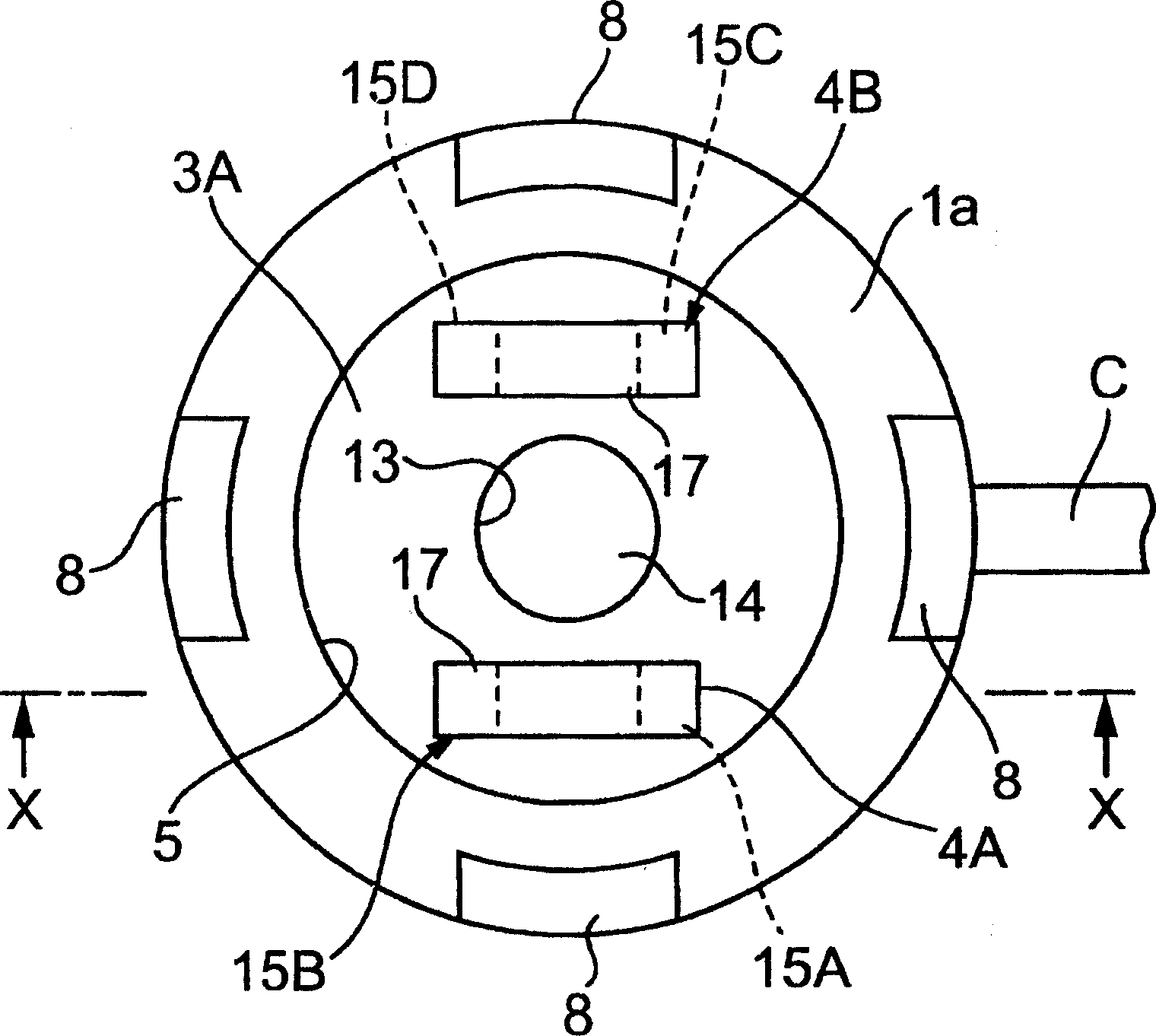
[0055] Embodiment 1 of the present invention consists of Figure 1 to Figure 9 Shows. figure 1 It is a structural explanatory diagram of Embodiment 1 of the liquid leakage detector of the present invention, figure 2 It is the front view of the sensor part of this liquid leakage detector, image 3 is a bottom view of the sensor section, Figure 4 is a cross-sectional view of the sensor section, Figure 5 is along image 3 Partially omitted cross-sectional view of the X-X line in the middle, Image 6 is along Figure 4 Partially omitted cross-sectional view of the Y-Y line in the middle.
[0056] The liquid leakage detector F of the present invention is composed of a sensor unit A for detecting a liquid leakage, and a device main body (amplifier unit) B.
[0057] This equipment main body (amplifier part) B has a signal transmission circuit, a level setting part, a comparison part, a liquid leakage output part, and a display part (none of which are shown in the figure), ...
Embodiment 2
[0077] Embodiment 2 of the present invention is in Figure 10 to Figure 13 shown in .
[0078] In Embodiment 2 of the present invention, in the sensor part A, the female thread part 26 is formed on the inner surface of the hollow cylindrical guide part 13 provided on the base body 3, and the female thread part 26 is added to the mounting hole G, The other structures are the same as those of Embodiment 1 of the present invention. Therefore, it is possible to install the sensor unit A on the sensor installation surface 30 without using the nut member 32 .
[0079] That is, if Figure 11 As shown, by screwing the internal thread portion 26 of the mounting hole G of the sensor part A to the stud bolt 31, the sensor part A is rotated, as shown in FIG. Figure 12 As shown, the sensor part A is installed on the sensor installation surface 30 . In addition, the operation of the liquid leakage detector F is the same as that of the first embodiment of the present invention described...
Embodiment 3
[0082] Embodiment 3 of the present invention is in Figure 14 to Figure 17 shown in .
[0083] In Embodiment 3 of the present invention, in the sensor part A, the internal thread part 26 is formed on the inner surface of the hollow cylindrical guide part 13 provided on the base body 3, and the cover body 2 is not provided with the hole part 10. The internal thread portion 26 is added to the hole G, and the mounting hole 10 is a bottomed hole. The other configurations are the same as those in the first embodiment of the present invention described above. Therefore, it is possible to install the sensor unit A on the sensor installation surface 30 without using the nut member 32 .
[0084] That is, if Figure 15 As shown, by screwing the internal thread portion 26 of the mounting hole G of the sensor part A to the stud bolt 31, the sensor part A is rotated, as shown in FIG. Figure 16 As shown, the sensor part A is installed on the sensor installation surface 30 . In this cas...
PUM
 Abstract
Description
Claims
Application Information