Built-in antenna and its manufacturing method and fixing method, and electronic apparatus asing same

A manufacturing method and technology of fixing method, applied in the directions of antenna support/installation device, antenna, resonant antenna, etc., can solve the problems of deterioration of antenna characteristics, problems in manufacturing efficiency, deterioration of antenna performance, etc., so as to reduce installation man-hours and improve reliability. sexual effect

Inactive Publication Date: 2004-06-30
HITACHI CABLE +1
View PDF2 Cites 5 Cited by
  • Summary
  • Abstract
  • Description
  • Claims
  • Application Information

AI Technical Summary

Problems solved by technology

[0003] However, with the expansion of the mobile phone market, the structure of fixing the antenna plate obtained by stamping a copper plate with adhesive tape and the structure of fixing it with screws after fixing it by heat welding have problems in terms of manufacturing efficiency.
In addition, there is a problem of limiting the degree of freedom in design and three-dimensional design required for mobile phones, and deteriorating antenna performance
[0004] According to the existing built-in antenna, it can be considered that in the first method, the process of affixing adhesive tape or the like to the built-in antenna body and the method of fixing the built-in antenna body in the mobile phone are not suitable for mass production. Adhesive tape etc. are the main cause of deterioration of antenna characteristics
[0005] In addition, in the second method, there are problems in that a dedicated thermal welding jig must be used, and individual operations must be performed separately, and in addition, because there is a screw fixing process, it is not suitable for mass production

Method used


Image

  • Built-in antenna and its manufacturing method and fixing method, and electronic apparatus asing same
  • Built-in antenna and its manufacturing method and fixing method, and electronic apparatus asing same
  • Built-in antenna and its manufacturing method and fixing method, and electronic apparatus asing same

Examples


Embodiment Construction

[0032] Hereinafter, embodiments of the present invention will be specifically described with reference to the drawings.

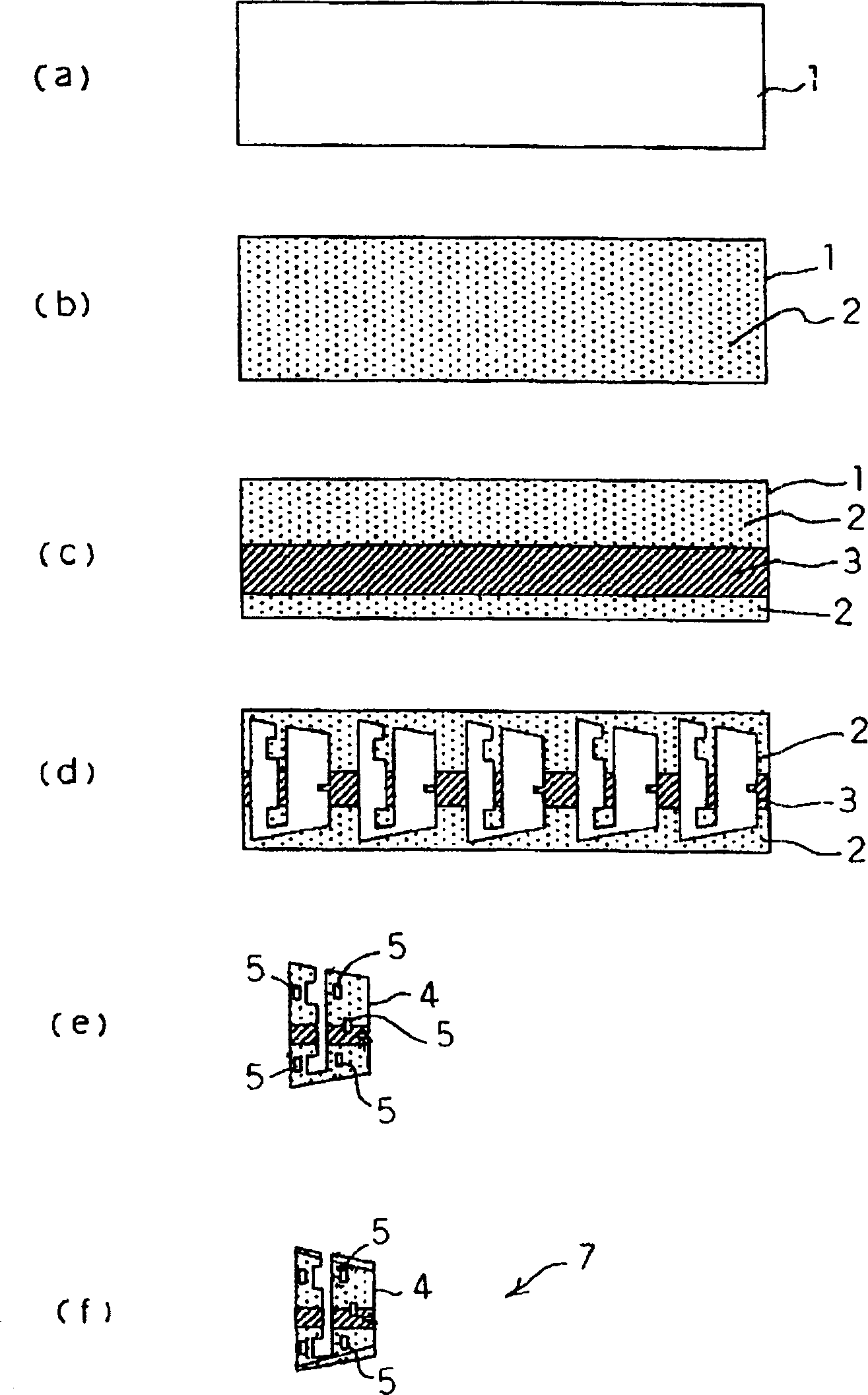
[0033] figure 1 (a) to (f) are process diagrams showing one embodiment of the method for manufacturing a built-in antenna according to the present invention.

[0034] First, if figure 1 Shown in (a), prepare rectangular metal plate (such as copper plate) 1, in order to prevent this metal plate 1 from being corroded, it is immersed in the Ni plating solution, and as figure 1 As shown in (b), the Ni plating layer 2 is formed on the entire surface of the metal plate 1 .

[0035] Next, on the surface of this Ni-plated layer 2, use masking tape (not shown) to stick to the area outside the bar-shaped area formed, it is immersed in the Au plating solution, such as figure 1 As shown in (c), the Au plating layer 3 for stabilizing the conductivity of the contact portion (the power supply terminal and the ground terminal described later) is formed on the stripe...


PUM


Abstract

Provided is a built-in antenna with high productivity, an electronic device using the built-in antenna, a method for manufacturing the built-in antenna and a method for installing the built-in antenna. When this built-in antenna 7 is manufactured, a plurality of penetrating holes 5 through which a plurality of protrusions 16 penetrate when the built-in antenna 7 is fixed to a housing side to be built in are progressively or simultaneously punched by a progressive die that can continuously perform processing from punching and bending. This forms the plurality of penetrating holes 5 in an area to be a radiating portion of a metal plate 1, stably performs the processing and improves the productivity of the built-in antenna 7. In addition, because of the existence of the penetrating holes 5, a special tool is not required, attaching man-hour is reduced, and the stability of attaching work is improved.

Description

technical field [0001] The present invention relates to a built-in antenna, an electronic device using the built-in antenna, a method of manufacturing the built-in antenna, and a method of fixing the built-in antenna. Background technique [0002] Generally, the built-in antenna used in mobile terminals such as mobile phones and personal computers is connected to the printed circuit board, the cover of the mobile phone body, etc., using the following structure, that is, the plastic molded body such as the printed circuit board and the cover. After the positioning protrusion penetrates the through hole for positioning, it is bonded with adhesive tape or the like to the antenna board (conductor plate) that punches the copper plate into a predetermined shape together with the through hole for positioning (for the first connection method, refer to, for example, the patent document 1 Japanese Patent Laying-Open No. 10-163748 (page 2, figure 2 )), or while fixing the positioning ...

Claims


Application Information

Patent Timeline
Patent Type & Authority Applications(China)
IPC IPC(8): H01P11/00H01Q1/12H01Q1/24H01Q9/04H01Q13/10
CPCH01Q9/0407H01Q1/1207H01Q1/243H01Q1/12
Inventor 横地利之高场进一杉山刚博
Owner HITACHI CABLE
Why Eureka
Try Eureka