Heating unit fixing device

A technology for fixing devices and heating elements, which is applied in household heating, household heating, heating methods, etc. It can solve the problems that cannot meet the requirements of thermal expansion and extension of heating elements, the installation position of heating elements is not designed, and affect the normal use of heating elements, etc. , to reduce the difficulty of installation and labor intensity, improve the safety of use, reduce the difficulty of molding and the effect of mold manufacturing cost

Inactive Publication Date: 2014-07-02
FUZHOU AQUAPOWER ELECTRIC WATER HEATER
View PDF5 Cites 3 Cited by
  • Summary
  • Abstract
  • Description
  • Claims
  • Application Information

AI Technical Summary

Problems solved by technology

However, this heating element does not have a design installation position, resulting in the following problems in use:
[0006] 1. The main body of the heating element is made of aluminum, and the surface temperature can reach up to 350°C. The general plastic mounting bracket cannot withstand such a high temperature;
[0007] 2. The metal material has good thermal conductivity, so the metal mounting bracket can easily transfer the heat of the heating element to other places, resulting in unnecessary heat loss and potential safety hazards;
[0008] 3. The heating element expands with heat and contracts with cold during work, which causes the size of the heating element to change, mainly elongating or shortening along the length direction. This phenomenon is called "thermal expansion and extension", while the length direction is "Extension direction", the traditional fixed installation device cannot meet the thermal expansion and extension requirements of this type of heating element, making the heating element easily restricted and causing bending deformation, which affects the normal use of the heating element

Method used


Image

  • Heating unit fixing device
  • Heating unit fixing device
  • Heating unit fixing device

Examples


Embodiment Construction

[0041] In order to describe the technical content, structural features, achieved goals and effects of the present invention in detail, the following will be described in detail in conjunction with the embodiments and accompanying drawings.

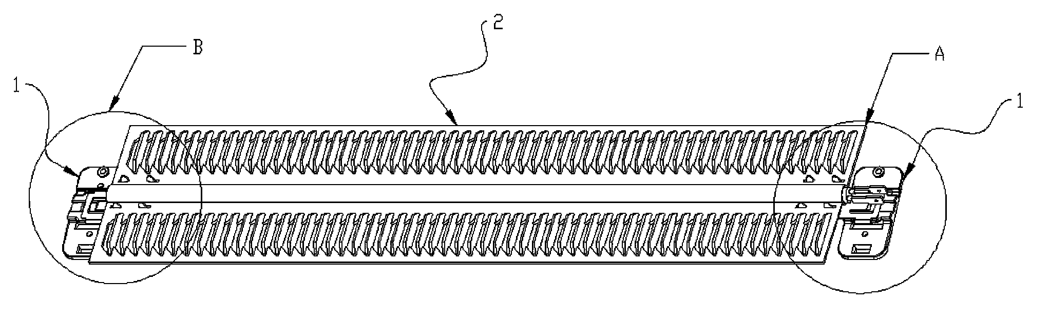
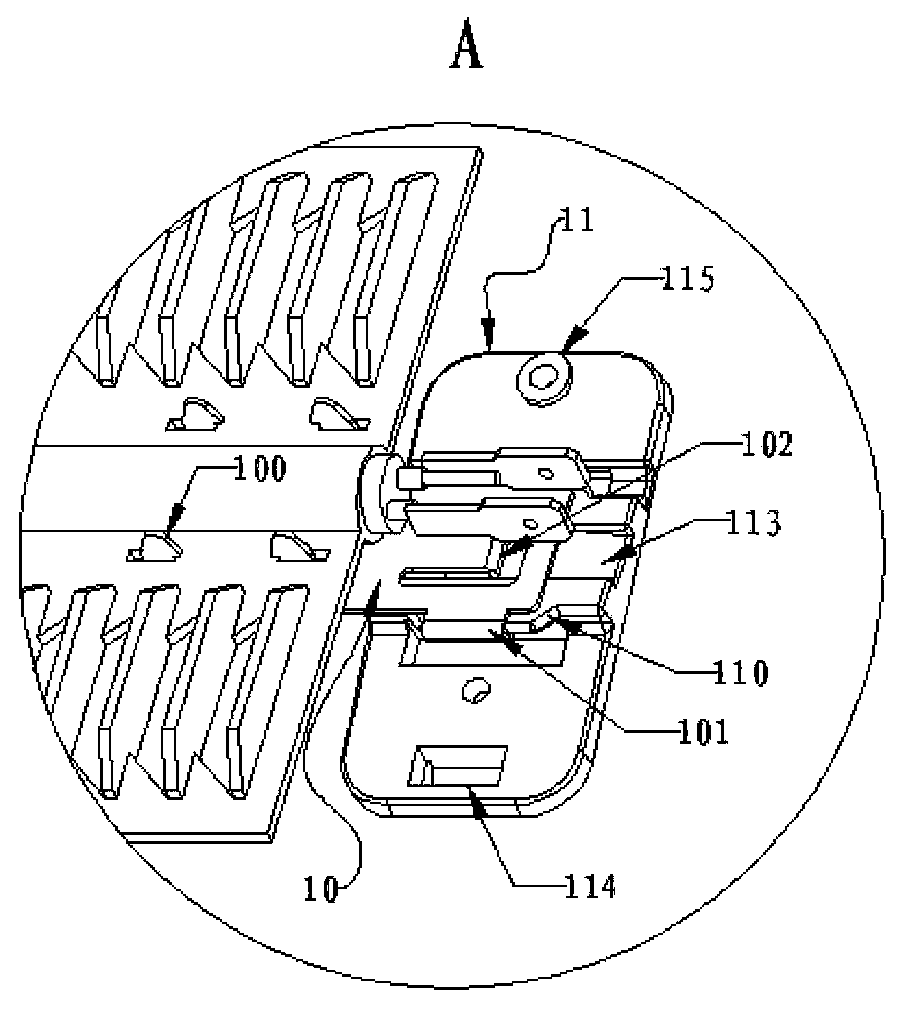
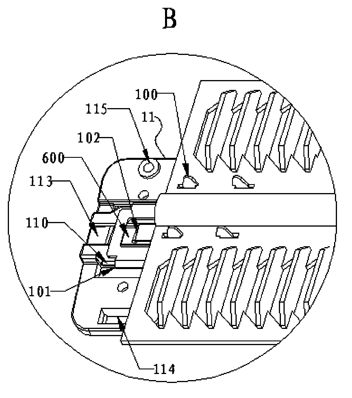
[0042] see Figure 1 to Figure 5 As shown, the heating element fixing device 1 of this embodiment is installed on the left and right ends of the heating element 2, and includes a bracket 10 and a base 11. The bracket 10 is provided with a first hook 100, a chute 101 and a second hook 102, the base 11 is provided with a slide rail 110 matching with the chute 101 and a positioning groove 111 snap-connected with the second hook 102, the bracket 10 passes through the first clip The hook 100 is snap-connected with the heating element 2 , the bracket 10 is slidably arranged on the slide rail 110 through the chute 101 and is snap-connected with the positioning groove 111 by the second hook 102 fixed on the base 11, the sliding direction of the b...


PUM


Abstract

The invention relates to a heating unit fixing device. The heating unit fixing device is arranged at the left end and the right end of a heating unit and comprises a support and a base, wherein the support is provided with first clamping hooks, sliding grooves and a second clamping hook, the base is provided with a sliding rail and a locating groove, the sliding rail is matched with the sliding groove, the locating groove is in snap joint with the second clamping hook, the support is in snap joint with the heating unit through the first clamping hooks, the support is arranged on the sliding rail in a sliding mode through the sliding grooves and is fixed on the base through snap joint between the second clamping hook and the locating groove, and the sliding direction of the support is consistent with the extending direction of the heating unit. In addition, when the second clamping hook is clamped in the locating groove, a gap is formed between the second clamping hook at least one of the left end and the right end of the heating unit and the locating groove. The heating unit fixing device is simple in structure, convenient to install, and capable of meeting the thermal expansion extension requirement of the heating unit.

Description

technical field [0001] The invention relates to a heating element fixing device, in particular to a fixing device for a sheet aluminum fin heating element. Background technique [0002] With the improvement of people's living standards and the continuous acceleration of the pace of life, people's requirements for the safety and efficiency of electrical appliances are also getting higher and higher. Natural convection electric heaters are more and more popular in heating indoors in winter due to their good safety, quiet work, and non-drying of indoor heating. As for the heating elements of convection electric heaters, mica heating frames and PTC corrugated heating elements are mainly used, but these two heating elements have certain disadvantages: [0003] The mica heating element adopts the exposed heating wire to be energized and heated, which is prone to safety hazards such as leakage and fire in the event of a failure; [0004] Although the PTC corrugated heating elemen...

Claims


Application Information

Patent Timeline
Patent Type & Authority Applications(China)
IPC IPC(8): F24D19/00
Inventor 陈建亮孙宗闽
Owner FUZHOU AQUAPOWER ELECTRIC WATER HEATER
Why Eureka
Try Eureka