Tension locking device for ring

A locking device and tension technology, applied in earrings, applications, clothing, etc., can solve the problems of detachment from the earlobe, inability to change, weakening the fixing force of the plate spring 30, etc.

Inactive Publication Date: 2005-06-15
金裕坤
View PDF0 Cites 0 Cited by
  • Summary
  • Abstract
  • Description
  • Claims
  • Application Information

AI Technical Summary

Problems solved by technology

However, the above-mentioned supporting piece 24 does not actually fully play the role of dispersing the fatigue stress. In this prior art tension locking device 20, the fatigue stress generated due to the repeated tension of the plate spring 30 is basically concentrated. As the fixed fulcrum of the fixed piece 23 part, so the fixed piece 23 part is very prone to partial fracture, and because it is only pressed by the fixed piece 23, this not only weakens the fixing force to the plate spring 30, but also has The disadvantage of being unable to change or increase the tension force of the plate spring 30 on the tension locking device 20
[0007] Due to the above-mentioned shortcomings and problems in the prior art, when the tension locking device 20 is repeatedly used (rotating action), it often occurs that the tension force is reduced due to the fatigue limit of the fixed piece 23 and the plate spring 30, thereby reducing the earring. 1 performance, so that the earring 1 hanging on the earlobe is loose or even detached from the earlobe

Method used


Image

  • Tension locking device for ring
  • Tension locking device for ring
  • Tension locking device for ring

Examples


Embodiment Construction

[0022] The specific embodiments of the present invention will be further described in detail below with reference to the accompanying drawings.

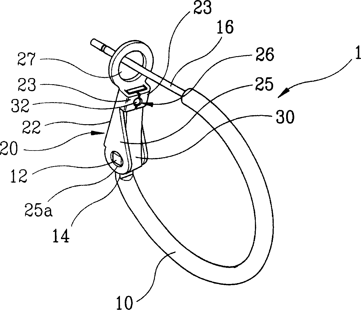
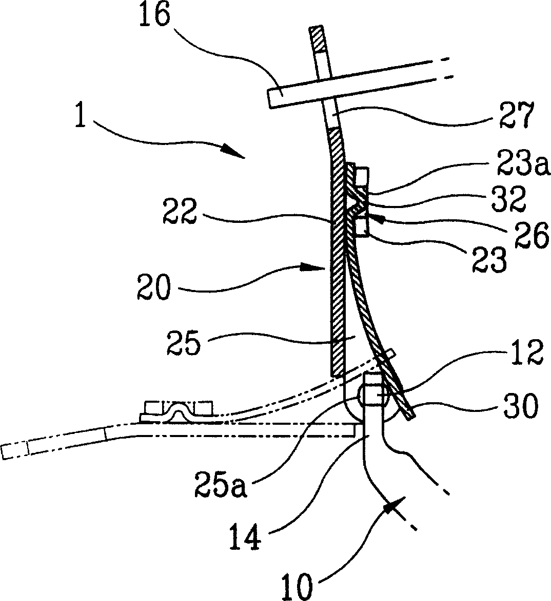
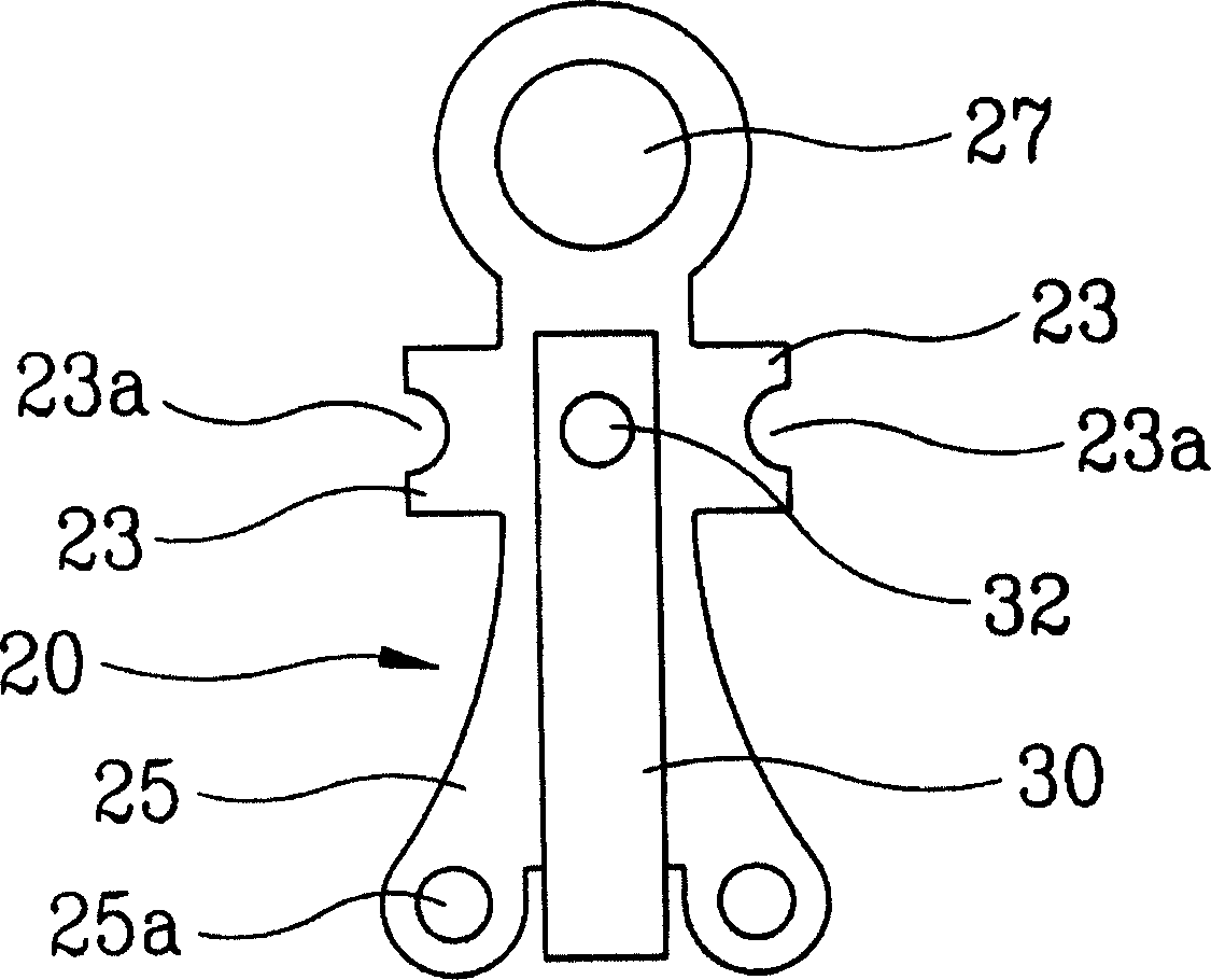
[0023] figure 1 It is a schematic diagram of the structure of the earring with the tension locking device installed according to the present invention, figure 2 It is a partial enlarged cross-sectional schematic diagram of the combined state of the tension locking device of the present invention and the earring body, Figure 3a It is a schematic diagram of the unfolded state of the locking device before the plate spring is combined with the locking device body constituting the tension locking device of the present invention, Figure 3b It is a cross-section of the plate spring of the present invention and its partial enlarged schematic diagram. In the following description of the present invention, the same parts as the tension locking device of the earring in the prior art will be described with the same reference numerals.

[...


PUM


Abstract

The invention relates to a tension locking device for earrings. The feature of this device is that an embossed protrusion is formed on one side of the plate spring of the tension locking device designed to be able to pick and hang earrings on the earlobe arbitrarily, and the fixing pieces formed on both sides of the tension locking device are formed by bending To fix and support the embossed protrusion, and make the embossed protrusion be movably clamped by the fixing piece, thereby not only preventing the separation or disengagement of the plate spring, but also preventing damage to the Stress concentration occurs locally on the fixed piece or the plate spring, fundamentally preventing the fixed piece on the tension lock device or the plate spring connected to the tension lock device from being partially broken. In addition, since the present invention can realize the tension action of the tension locking device with a small force, the feeling and effect when the user wears the earrings is improved.

Description

Technical field [0001] The present invention relates to a tension locking device, in particular to a tension locking device applied to earrings which can be freely hung on or removed from the earlobe. Background technique [0002] In general, earrings are roughly divided into two forms. One is earrings that can be used even without punching the earlobe, and the other is earrings that can be used without punching the earlobe. Most of these earrings have tension locks that make it easy to put on or take off the earrings. [0003] see Figure 4 and Figure 5 , which represents a prior art tension locking device used on earrings. [0004] like Figure 4 and Figure 5 As shown, the tension locking device 20 is integrally formed with a fixing hole 27 which can clamp and support the fixing end 16 of the earring body 10 on one end of the locking device body 22 . The other end of the locking device body 22 is bent toward the inside of the locking device body 22 , and a hinge hol...

Claims


Application Information

Patent Timeline
Patent Type & Authority Applications(China)
IPC IPC(8): A44C7/00
CPCA44C7/004A44C7/00
Inventor 金裕坤
Owner 金裕坤
Why Eureka
Try Eureka