Apparatus for splicing yarns pneumatically

A yarn and splicing channel technology, which is applied in the field of yarn splicing devices, can solve the problems of no yarn, not suitable for the textile industry, unsuitable yarn, etc., and achieve the effect of uniform appearance

Inactive Publication Date: 2005-06-22
SAURER GMBH & CO KG
View PDF6 Cites 14 Cited by
  • Summary
  • Abstract
  • Description
  • Claims
  • Application Information

AI Technical Summary

Problems solved by technology

Such double piecing, although more durable, does not have a nearly uniform yarn piecing and is therefore less suitable for use in t

Method used


Image

  • Apparatus for splicing yarns pneumatically
  • Apparatus for splicing yarns pneumatically
  • Apparatus for splicing yarns pneumatically

Examples


Embodiment Construction

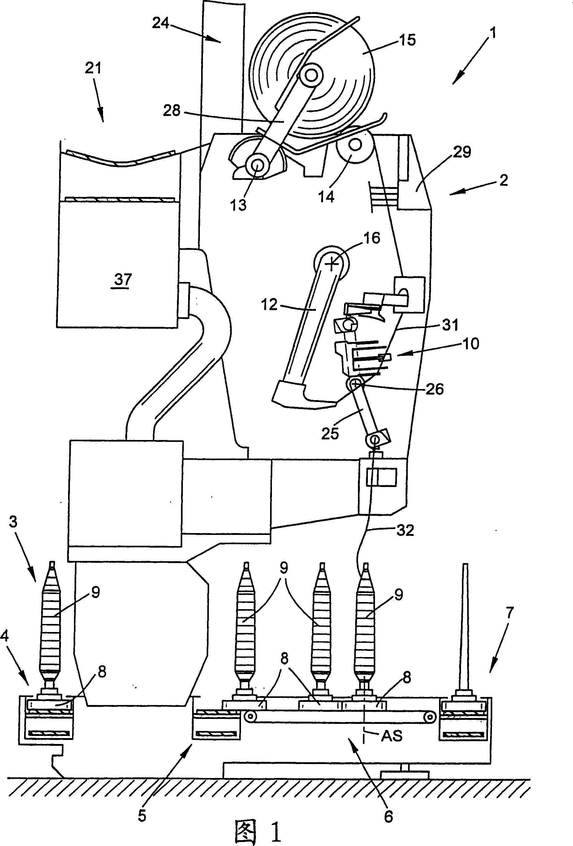
[0042] In FIG. 1 , a textile machine for producing cross-wound bobbins, in the embodiment a so-called automatic cross-winder, is shown schematically in side view, generally indicated with the reference numeral 1 . Such an automatic cross-winding winder 1 usually has a plurality of homogeneous stations, in this case winding heads 2, between its end frames (not shown).

[0043] On this winder 2 , the bobbin 9 produced on the ring spinning frame is rewound into a large-volume cross-wound bobbin 15 , as is well known and therefore does not need to be described in detail. After its completion, the cross-wound bobbins 15 are transferred to a cross-wound bobbin conveyor 21 arranged along the machine by means of an automatically working service unit, preferably a cross-wound bobbin changer (not shown), And is transported to a bobbin loading and unloading station or similar device arranged on the end side of the machine.

[0044] Furthermore, this automatic cross-winding winder 1 has ...


PUM


Abstract

The invention relates to a yarn splicing device for pneumatically joining yarns, especially elastic yarns, with a splicing body having a vacuum-loadable splicing channel which can be operated by means of a The covering element is closed and, moreover, a support is arranged in the region of the splicing channel, which supports the fixing of the yarn ends. According to the invention, it is provided that the supporting element consists of a spring wire (36) and a cover element (23), wherein the spring wire (36) is positioned in an opposite position in the spliced ​​body (19). In the groove (35) that moves angularly in the splicing channel (20), that is, the yarn ends (31, 32) to be spliced ​​are clamped between the covering element (23) and the spring wire ( 36) Between.

Description

technical field [0001] The invention relates to a yarn splicing device for pneumatically joining yarns, especially elastic yarns, according to the preamble of claim 1 . Background technique [0002] Yarn splicing devices for pneumatically joining yarns have long been known in connection with automatic cross-winding winders and are described in detail in numerous patent documents such as DE4005752A1 or DE4420979A1. [0003] With this known yarn splicing device, it is possible to pneumatically join two yarn ends, for example by yarn breakage or controlled yarn clearer cutting, into a nearly uniform joint of the yarn. [0004] This means that the upper yarn wound on the surface of the cross-wound bobbin is sucked up by the yarn suction nozzle and introduced into the splicing channel of the splicing body of the yarn splicing device. [0005] Almost at the same time, the lower thread is picked up by a bobbin in the unwinding position via a clamping bobbin and is also placed in t...

Claims


Application Information

Patent Timeline
IPC IPC(8): B65H69/06
CPCB65H69/061B65H2701/319
Inventor 德特勒夫·福尔
Owner SAURER GMBH & CO KG
Why Eureka
Try Eureka