Cooling device, manufacturing method, and manufacturing line for hot rolled steel band

A technology of cooling device and manufacturing method, which is applied in the direction of workpiece cooling device, quenching device, metal rolling, etc., and can solve the problems of large flow rate attenuation, insufficient increase of cooling water, and inability to cool the upper and lower surfaces of steel strips, etc.

Inactive Publication Date: 2005-06-22
JFE STEEL CORP
View PDF0 Cites 21 Cited by
  • Summary
  • Abstract
  • Description
  • Claims
  • Application Information

AI Technical Summary

Problems solved by technology

[0007] 1) The hot-rolled steel strip, because its front end comes out of the finishing mill to the coiler, is in a state of no tension. On the output roller table, it is conveyed while vibrating up and down. This technology cools such a steel strip without tension. Since this up and down vibration is promoted, the amount of cooling water cannot be increased sufficiently. For example, it is impossible to cool a steel strip with a thickness of 3mm at a cooling rate of 200°C/s or more.
[0008] 2) In

Method used


Image

  • Cooling device, manufacturing method, and manufacturing line for hot rolled steel band
  • Cooling device, manufacturing method, and manufacturing line for hot rolled steel band
  • Cooling device, manufacturing method, and manufacturing line for hot rolled steel band

Examples


Embodiment

[0076] Use settings like Figure 13 The cooling device of the hot-rolled strip of the present invention shown is as Figure 14 In the production line of hot-rolled steel strip shown, the rough profile of carbon steel with a plate thickness of 30mm and a plate width of 1000m is rolled through a finishing mill consisting of 7 rolling stands at a conveying speed of 700mpm and a finishing temperature of 850°C. After forming a steel strip with a thickness of 3mm, the steel strip was cooled to 550°C at a cooling rate of about 700°C / s, and then cooled using the existing cooling device 8 so that the coiling temperature was 500°C. And, the water density when the cooling rate is about 700°C / s is 7500L / min·m 2 .

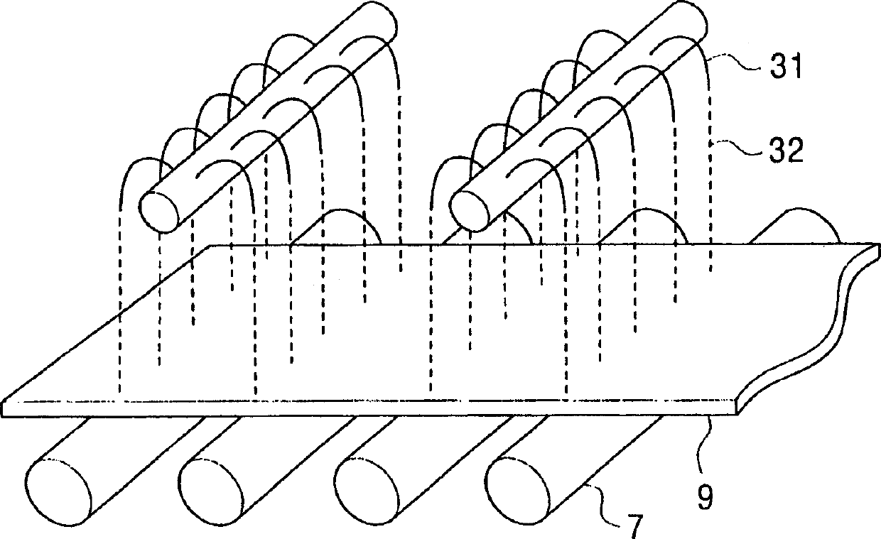
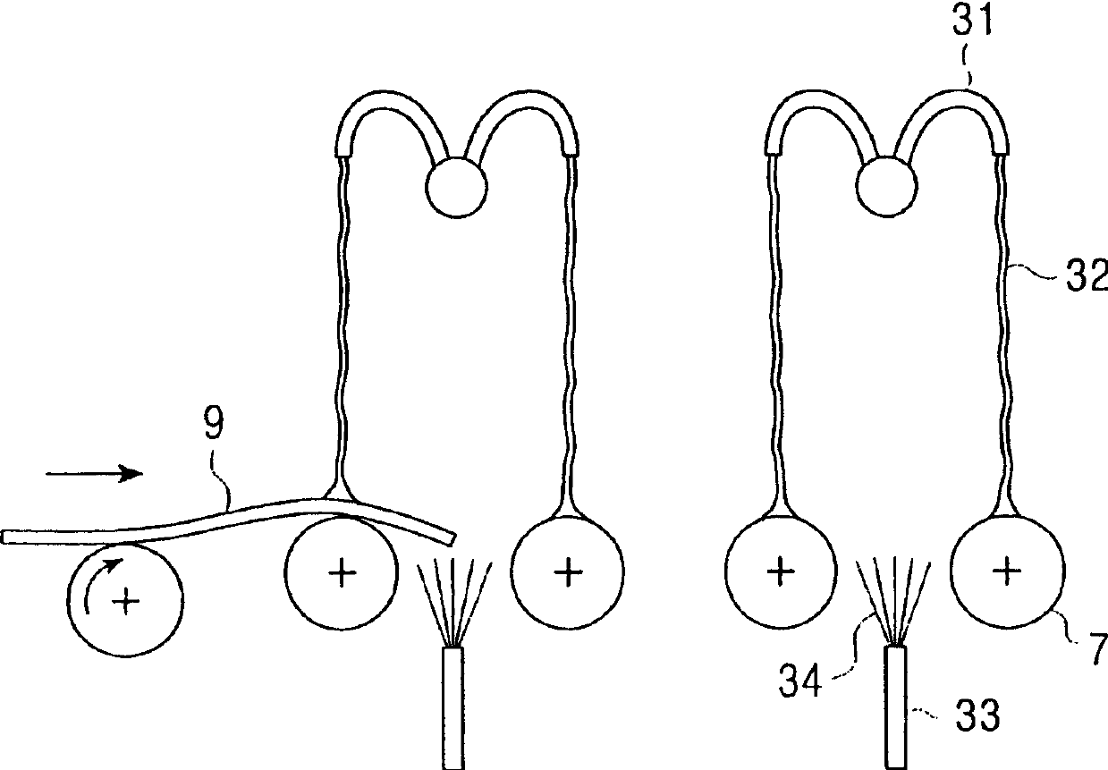
[0077] Such as Figure 13 As shown, the lower surface cooling device 4a has a plurality of conveying rollers 7 with a diameter of 300mm arranged at a pitch of 500mm in the longitudinal direction. The lower surface protection member 10a of the plate thickness 25mm flat plate...


PUM


Abstract

The present invention relates to a cooling apparatus for hot rolled steel strip comprising: an upper means for cooling an upper side of a steel strip transported by transporting rolls after hot rolling, located above the upper side of the steel strip; and a bottom means for cooling the bottom side of the steel strip, located under the bottom side of the steel strip, each means for cooling including: a protecting member having at least one cooling water hole slotted thereon, located near the surface of the steel strip; at least one cooling water header, located across the steel strip from the protecting member; and cooling water injection nozzles for injecting cooling water vertically onto the surface of the steel strip through the cooling water hole, projected on the cooling water header, wherein the top of the cooling water injection nozzle is positioned at a longer distance from the surface of the steel strip than the surface of the protecting member facing to the surface of the steel strip. The present invention allows to constantly transport the steel strip after hot rolling and to rapidly and homogeneously cool it.

Description

technical field [0001] The present invention relates to a cooling device for a hot-rolled steel strip after hot rolling, a method for manufacturing a hot-rolled steel strip using the device, and a production line for a hot-rolled steel strip. Background technique [0002] Generally, the hot-rolled steel strip is heated to a specified temperature in a heating furnace, and the heated steel slab is rolled into a rough section with a specified thickness through a rough hot rolling mill, and the rough section is passed through a rolling mill consisting of multiple rolling stands. The finishing mill rolls the steel strip with a specified thickness, and the rolled steel strip is conveyed through the cooling device on the output roller table while being cooled, and then coiled by the coiler. Here, the run-out table refers to a conveying device for the hot-rolled steel strip installed downstream of the finishing mill, and the steel strip is conveyed by a plurality of conveying roller...

Claims


Application Information

Patent Timeline
IPC IPC(8): B21B39/00B21B39/10B21B45/02C21D1/667C21D8/02C21D9/573
CPCB21B45/0218B21B45/0233B21B45/0281C21D1/667C21D8/0263C21D9/573
Inventor 藤林晃夫佐佐木成人日野善道渡边厚
Owner JFE STEEL CORP
Why Eureka
Try Eureka