Self locking, breaking up and destructing safety syringe

A safe, syringe technology, applied in the field of medical devices, can solve the problems of difficult to achieve blockage, cannot be used normally, and difficult to process, and achieve the effects of reducing residual flow, good effect and simple process

Inactive Publication Date: 2005-06-29
陈嘉农
View PDF1 Cites 0 Cited by
  • Summary
  • Abstract
  • Description
  • Claims
  • Application Information

AI Technical Summary

Problems solved by technology

The process of making the plug and piston of the above-mentioned syringe integrated is relatively difficult, the production yield is low, and the cost is high. When in use, due to the good elasticity of the rubber, the cut at the rear end of the plug is not easy to break, and it is difficult to achieve the plugging effect. ; If it is bonded, it is difficult to accurately locate the plug at the center of the piston, because the bonding area is small, so it is easy to fall off when not in use, and cannot be used normally

Method used


Image

  • Self locking, breaking up and destructing safety syringe
  • Self locking, breaking up and destructing safety syringe
  • Self locking, breaking up and destructing safety syringe

Examples


Embodiment 1

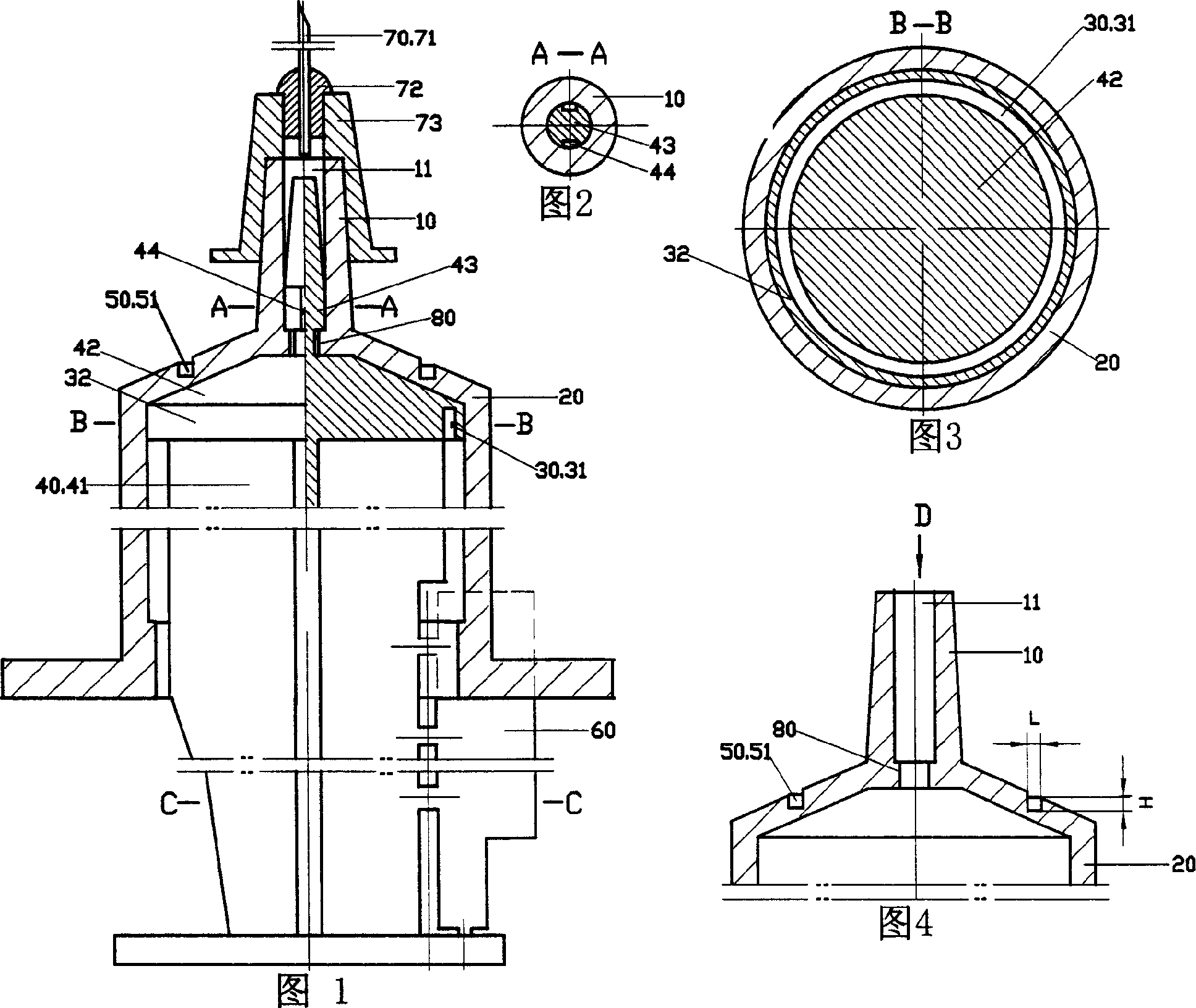
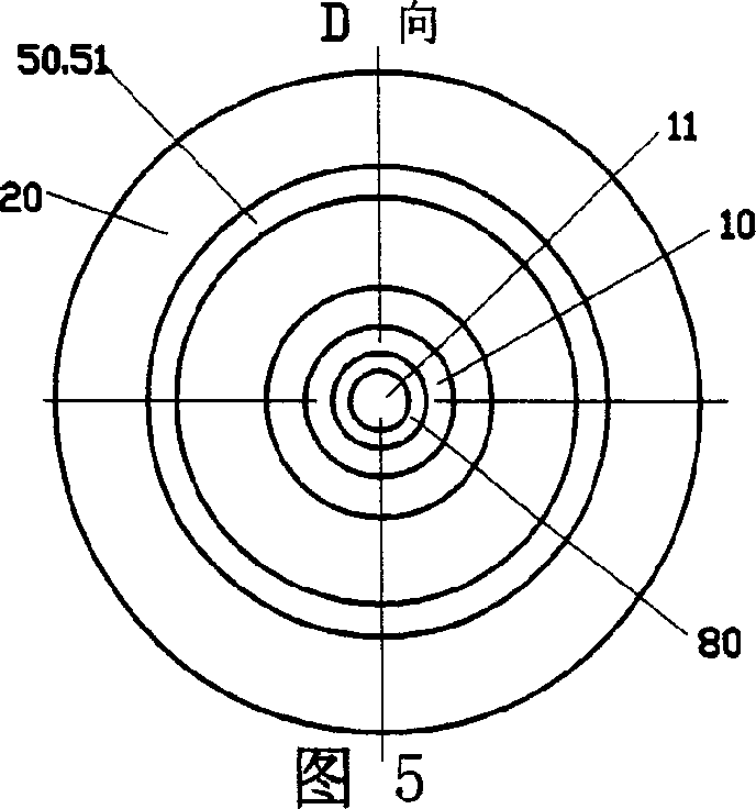
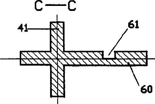
[0070] See Fig. 1 to Fig. 7, the material used in the syringe of this embodiment complies with the national standard. The injector of the present embodiment comprises cone 10, overcoat 20 and core rod 40; Cone head 10 has cone hole 11, and cone 10 and overcoat 20 are one piece; Core rod 40 has shaft 41 and top 42; Syringe also has Self-locking boss 80; a breakable structure 50 is provided on the jacket 20 or a breakable structure 50 is provided on the core rod 40; an elastic sealing structure 30 is provided on the top 42 of the core rod 40; see Fig. 1 and Fig. 1 3. The elastic sealing structure 30 of the top 42 of the core rod 40 is composed of an elastic groove 31 and a sealing ring 32. The elastic sealing structure 30 is integrated with the top 42 of the core rod 40; the outer wall of the sealing ring 32 of the elastic sealing structure 30 can be connected with The inner wall of the overcoat 20 is matched, and the outer diameter of the outer wall of the sealing ring 32 and t...

Embodiment 2

[0073] See Fig. 8 and Fig. 9, the use effect of the elastic sealing structure 30 of the syringe of this embodiment is basically the same as that of Embodiment 1, and the opening direction of the elastic groove 31 is upward; Groove 51; present embodiment is applicable to the syringe of specification above 5 milliliters; See Fig. 8, be provided with anti-poking slope 45 on protruding rod 43, can prevent that the parts that have been by self-locking are poked off. All the other are identical with embodiment 1.

Embodiment 3

[0075] Referring to Fig. 10 to Fig. 12, this embodiment is more suitable for syringes with specifications below 5 milliliters. The breakable structure 50 on the upper part of the overcoat 20 of the syringe in this embodiment is an unclosed arc-shaped groove 51; the number of the arc-shaped groove 51 is 1, and the arc of the arc-shaped groove 51 is 285°; Change the width of arc-shaped groove 51, the depth of arc-shaped groove 51, the quantity of arc-shaped groove 51, the radian of arc-shaped groove 51, thereby can change the size of the active force that makes breakable structure 50 break and disengage; See As shown in Fig. 10 and Fig. 12, an elastic groove 46 is provided on the protruding rod 43; the protruding rod 43 does not have an axial liquid guide groove 44; after the liquid medicine injection is completed, the last liquid medicine enters the cone head through the elastic groove 46 on the protruding rod 43 In the hole 11, to reduce the residual flow of the liquid medicin...


PUM


Abstract

The invention relates to a self-destructing syringe which comprises a tapered head, a casing and a core rod, wherein the tapered head is provided with a tapered head hole,the tapered head is integrated with the jacket, the core rod has a rod body and a top portion, the syringe also includes a self-locking boss, the top of the core rod is provided with a resilient sealing structure, the resilient sealing structure on the top of the core rod comprises a resilient slot and a sealing ring, the resilient sealing structure and the top of the core rod is an integrated member, the outer wall of the sealing ring of the resilient sealing structure can co-operate with the inner wall of the casing, the release arrangement of the casing is arranged on the outer wall on the upper portion of the casing, the release arrangement on the upper portion of the casing is an annular recess, the self-locking boss is arranged on the internal wall of the tapered hole, the top of the core rod includes a projected rod, the projected rod can co-operate with the tapered hole.

Description

technical field [0001] The invention relates to a self-destruct syringe, which belongs to the field of medical instruments. Background technique [0002] Chinese patent No. is 00219356.6, and the utility model patent description entitled "Blocking Type Disposable Syringe" discloses a syringe. The syringe includes a jacket, a core rod, and a piston; the jacket has a cone head, the cone head is provided with a cone head hole, and an annular boss is arranged in the cone head hole; the front end of the piston is provided with a plug, and the rear end of the plug has a cutout. There is a core bone in the center; the piston is connected with the plug, which can be made in one piece or bonded; the plug has a taper, and the front end is a small head; the inner wall of the annular boss is provided with at least one axial guide groove; A limit piece is provided at the rear of the rod. The process of making the plug and piston of the above-mentioned syringe integrated is relatively d...

Claims


Application Information

Patent Timeline
Patent Type & Authority Applications(China)
IPC IPC(8): A61M5/50
Inventor 陈嘉农邹志尚
Owner 陈嘉农
Why Eureka
Try Eureka