Eureka AIR delivers breakthrough ideas for toughest innovation challenges, trusted by R&D personnel around the world.

Transmission arrangement for transfer teeth of cylinder type sewing machine

A transmission structure, sewing machine technology, applied in sewing machine components, sewing equipment, cloth feeding mechanism, etc., can solve the problems of limited transmission device structure, inability to miniaturize the cylinder part, etc.

Inactive Publication Date: 2005-06-29
KORIN CO LTD
View PDF0 Cites 4 Cited by
  • Summary
  • Abstract
  • Description
  • Claims
  • Application Information

AI Technical Summary

Problems solved by technology

However, if you want to sew a cylindrical sewing product with a smaller diameter, this patent is limited by the structure of the transmission device and cannot make the cylindrical part more miniaturized

Method used


Image

  • Transmission arrangement for transfer teeth of cylinder type sewing machine
  • Transmission arrangement for transfer teeth of cylinder type sewing machine
  • Transmission arrangement for transfer teeth of cylinder type sewing machine

Examples


Embodiment Construction

[0013] Refer to the following Figure 1 to Figure 5 Preferred embodiments of the present invention will be described.

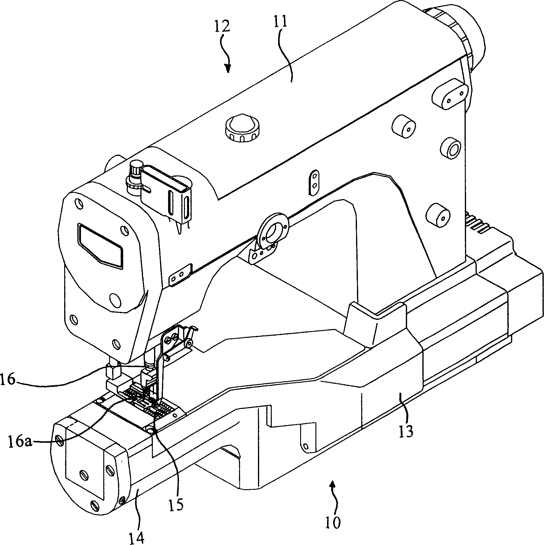
[0014] Such as figure 1 As shown, the sewing machine body 12 of the present invention is composed of a table part 10 and an arm part 11 located at the right end of the table part facing upwards. The machine unit 10 is composed of a rectangular box-shaped main unit 13 and a tubular cylindrical unit 14 protruding laterally from the main unit 13 . A needle plate 15 is provided on the cylindrical unit 14 .

[0015] A needle bar 16 with a plurality of sewing needles 16a is provided at the lower front end of the arm 11 facing the needle plate 15, and the needle bar 16 sews clothes reciprocally up and down along with a driving mechanism (not shown). On the cylindrical portion 14 below the needle plate 15, a shackle (not shown) is provided, and at the same time, as Figure 4 As shown, the cylindrical part 14 is provided with a forward transfer tooth 17 and a rear ...


PUM


Abstract

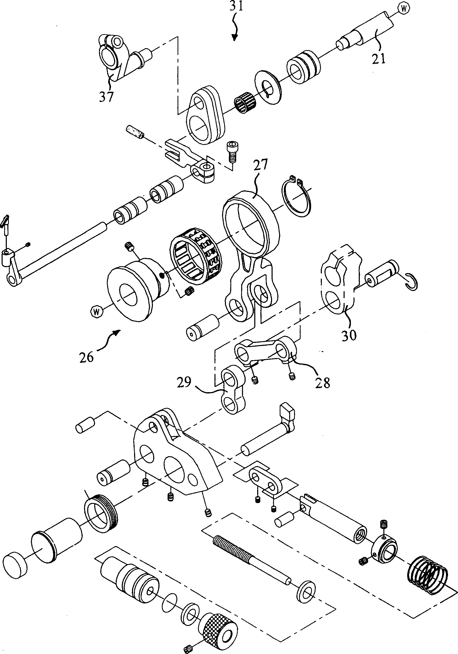
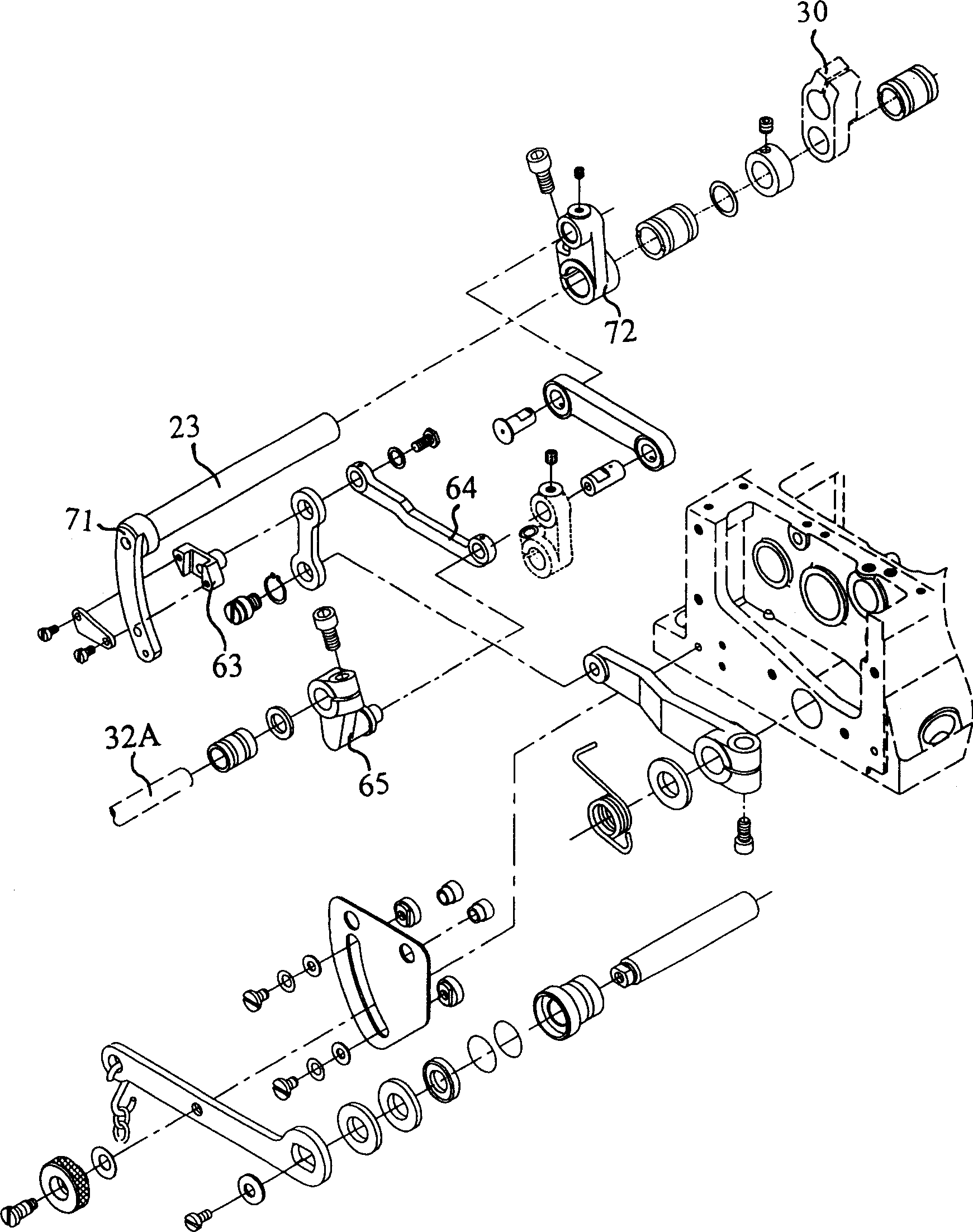
A transmission structure for the transmission teeth of a cylindrical sewing machine. The machine table of the sewing machine is composed of a rectangular box-shaped main part and a cylindrical part protruding sideways from the main part. A needle plate is arranged on the cylindrical part. , the cylindrical part is provided with a forward feed tooth and a rear feed tooth, the forward feed tooth and the rear feed tooth go in and out of the feed tooth grooves before and after the needle drop hole of the needle plate, through the transmission of the transmission mechanism, the The forward feeding gear and the rear feeding gear move circularly in an elliptical path; it also includes: the feeding gear assembly, the driving shaft, the motion conversion mechanism, the front and rear main shaft assembly of the transfer, the upper and lower transmission shaft assembly of the transfer, the fixed moving direction assembly, the first transfer Front and rear drive shaft assemblies and a second transfer front and rear drive shaft assembly.

Description

technical field [0001] The invention relates to a cylindrical sewing machine, in particular to a transmission structure of the transfer teeth of the cylindrical sewing machine. Background technique [0002] The table part of a general cylindrical sewing machine is composed of a rectangular box-shaped main part of the machine table and a cylindrical part protruding sideways from the main part of the machine table. needle board. The cylindrical part is provided with forward feeding teeth and rear feeding teeth, which go in and out of the holes for the feeding teeth before and after the needle drop hole of the needle plate, and the cylindrical part is provided with a hook and loop device which cooperates with the sewing needle to form a sewing purpose, and a drive The driving mechanism of the forward feed tooth and the rear feed tooth. [0003] The driving mechanism and power transmission mechanism of the cylindrical sewing machine for driving the forward and backward feeding...

Claims


Application Information

Patent Timeline
Patent Type & Authority Applications(China)
IPC IPC(8): D05B27/02
Inventor 蔡文呈
Owner KORIN CO LTD
Why Eureka
Eureka Blog
Learn More