
Mixed type helical groove dynamical and static pressure gas composite cylindrical bearing

A cylindrical bearing, dynamic and static pressure technology, applied in the direction of bearings, shafts and bearings, mechanical equipment, etc., can solve the problems of low load capacity, static pressure gas cylinder bearings do not fully utilize the load capacity and stiffness, reduce static pressure performance, etc.

Inactive Publication Date: 2005-06-29
HARBIN INST OF TECH
View PDF1 Cites 4 Cited by
  • Summary
  • Abstract
  • Description
  • Claims
  • Application Information

AI Technical Summary

Problems solved by technology

[0002] At present, the static pressure gas cylindrical bearings used in engineering, such as: high-speed static pressure air bearing electric spindle and other high-speed static pressure gas bearings, only use the static pressure air bearing to bear the load and provide stiffness, which are often encountered in practical applications. Due to the problems of low load-carrying capacity, low stiffness, and poor anti-interference ability, the hydrostatic gas cylinder bearings used in engineering do not make full use of the load-carrying capacity and stiffness that can be provided by the dynamic pressure effect of high speed or line speed ("Mechanical Design Manual" Volume II, Part Seven—Gas Lubricated Bearings. Fourth Edition, 2002, Chemical Industry Press; "Mechanical Design Manual", Volume Four, Chapter Nine, Chapter 40—Gas Bearings. Second Edition, 2003, Machinery Industry Press society.)
Utility model patent (application number: 87 2 15713) "herringbone groove dynamic and static pressure hybrid gas bearing" does not use sealing edge and pressure equalization groove, which reduces the static pressure performance: utility model patent (patent number: 94207681.8) "π-shaped The groove dynamic and static pressure hybrid gas bearing "does not use the sealing edge, which reduces the static pressure performance, and the dynamic pressure effect of the straight groove in the middle is not fully utilized.

Method used


Image

  • Mixed type helical groove dynamical and static pressure gas composite cylindrical bearing
  • Mixed type helical groove dynamical and static pressure gas composite cylindrical bearing
  • Mixed type helical groove dynamical and static pressure gas composite cylindrical bearing

Examples


Embodiment 1

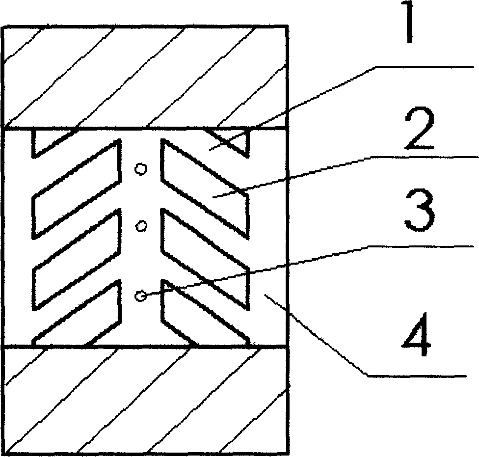
[0050] as attached figure 1 As shown, on the working face 1 of the cylindrical bearing, there are disjoint spiral dynamic pressure grooves 2 on both sides of the distribution circle of the static pressure air flotation air supply point 3, and the outer side of the spiral dynamic pressure groove 2 has an air sealing edge 4 The inner cylindrical surface is matched with a smooth outer cylindrical surface.

Embodiment 2

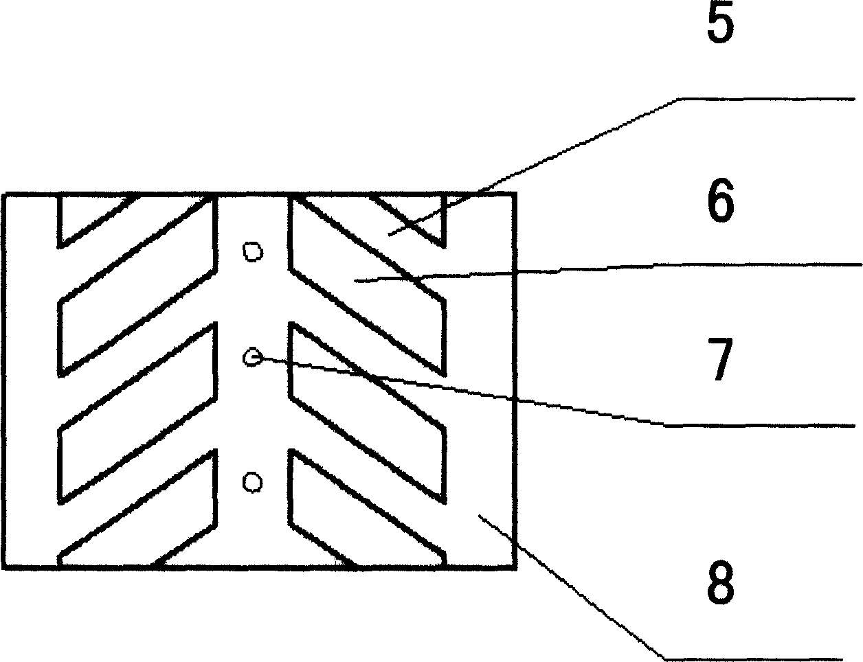
[0052] as attached figure 2 As shown, on the cylindrical bearing working surface 5, the static pressure air flotation air supply points 7 are distributed on both sides of the circle, and there are respectively unconnected helical dynamic pressure grooves 6, and the outer sides of the helical dynamic pressure grooves 6 have air sealing edges 8 The outer cylindrical surface is matched with a smooth inner cylindrical surface.

Embodiment 3

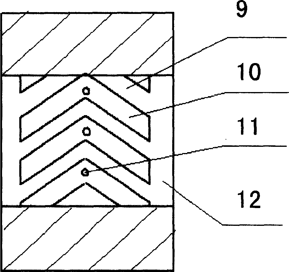
[0054] as attached image 3 As shown, there are connected spiral dynamic pressure grooves 10 on both sides of the distribution circle of the static pressure air flotation gas supply point 11 on the cylindrical bearing working surface 9, and the outer side of the spiral dynamic pressure groove 10 has a sealing edge 12. Inner cylindrical surface with smooth outer cylindrical surface.


PUM


Abstract

The "hybrid spiral groove dynamic and static pressure gas composite cylindrical bearing" of the present invention relates to a high-speed, high rigidity, large load ultra-precision spiral groove dynamic and static pressure gas composite cylindrical bearing. On the working surface of the cylindrical bearing, the distribution of static pressure air flotation gas supply points There are herringbone dynamic pressure grooves on both sides of the circle. Without increasing the air consumption of the air bearing, the bearing capacity is increased by more than 30% compared with the traditional static pressure air bearing, and the bearing stiffness is 15% higher than that of the traditional static pressure air bearing. %above.

Description

technical field [0001] The invention relates to a dynamic and static pressure gas composite cylindrical bearing, especially an ultra-precision and ultra-high-speed gas cylindrical bearing. Background technique [0002] At present, the static pressure gas cylindrical bearings used in engineering, such as: high-speed static pressure air bearing electric spindle and other high-speed static pressure gas bearings, only use the static pressure air bearing to bear the load and provide stiffness, which are often encountered in practical applications. Due to the problems of low load-carrying capacity, low stiffness, and poor anti-interference ability, the hydrostatic gas cylinder bearings used in engineering do not make full use of the load-carrying capacity and stiffness that can be provided by the dynamic pressure effect of high speed or line speed ("Mechanical Design Manual" Volume II, Part Seven—Gas Lubricated Bearings. Fourth Edition, 2002, Chemical Industry Press; "Mechanical D...

Claims


Application Information

Patent Timeline
IPC IPC(8): F16C32/06
Inventor 谭久彬姚绍明金鹏马洪文杨文国金国良
Owner HARBIN INST OF TECH
Learn More