Traction control system for stationary reconnection locomotive

A technology of traction control system and re-connected locomotive, which is applied in general control system, control/regulation system, computer control, etc., and can solve the problems of cumbersome control methods and drivers

Active Publication Date: 2005-06-29
WUHAN ZHENGYUAN ELECTRIC
View PDF0 Cites 31 Cited by
  • Summary
  • Abstract
  • Description
  • Claims
  • Application Information

AI Technical Summary

Problems solved by technology

[0002] Sometimes two locomotives are used to achieve traction at the same time when a railway train is in operation. A driver’s cab is set at the junction of the t...

Method used


Image

  • Traction control system for stationary reconnection locomotive
  • Traction control system for stationary reconnection locomotive
  • Traction control system for stationary reconnection locomotive

Examples


Embodiment Construction

[0019] Below in conjunction with accompanying drawing and embodiment the present invention will be further described, but following embodiment should not be construed as limitation of the present invention

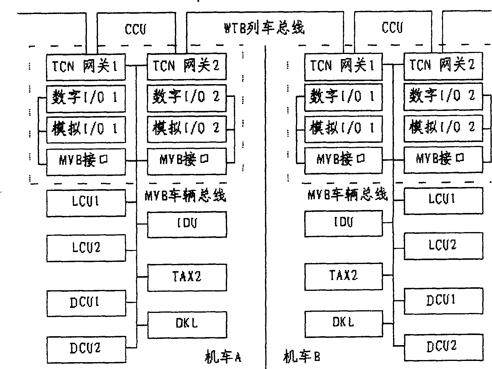
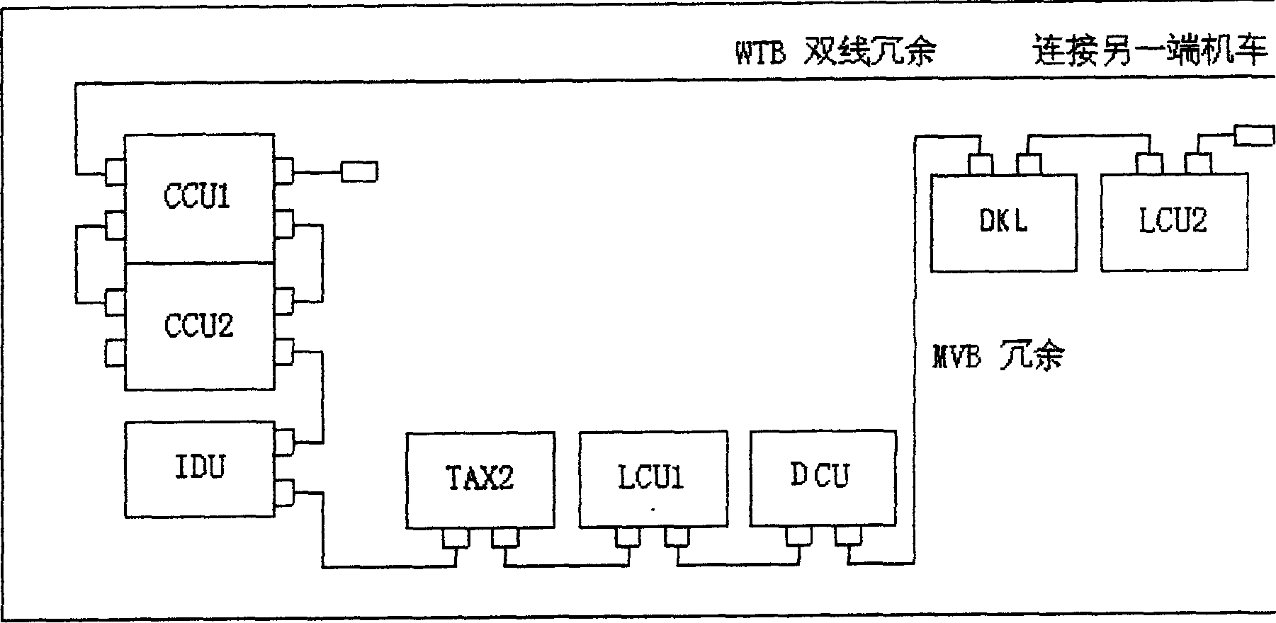
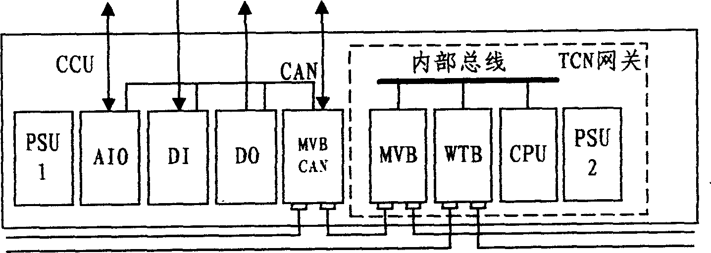
[0020] The invention is composed of two original SS3 electric locomotives through modification design, that is, canceling the driver's cab at the joint of the two locomotives and increasing the connecting channel to form the SS3B fixed and double-connected locomotive. For the two-section structure of the modified SS3B fixed reconnection locomotive, the present invention designs two sets of control systems for the two-section sub-locomotive, and uses the train communication network for reconnection control. Each locomotive has the same control system, consisting of central control unit (CCU), transmission control unit (DCU), logic control unit (LCU), display unit (IDU), operation safety monitoring unit (TAX2) and electropneumatic brake logic The control unit (DKL) is compos...


PUM


Abstract

This invention relates to a fixed connecting engine driving control system composed of two engines. Each engine has the same controlling system composed of central control unit, driving control unit, logic control unit, display unit, operation safety monitoring unit and electrical braking logic unit. It is characterized by the following: each engine control system adopts local network bus to make the data communication between module plates in each unit.

Description

technical field [0001] The invention belongs to a transmission control system for railway locomotives, in particular to a transmission control system for main traction control and digitalized automatic monitoring of the whole vehicle for SS3B fixed double-connected electric locomotives. Background technique [0002] Sometimes two locomotives are used to achieve traction at the same time when a railway train is in operation. A driver’s cab is set at the junction of the two locomotives, and the driver controls the normal operation of each unit of the two locomotives. This control method is relatively difficult for the driver. complicated. Contents of the invention [0003] The purpose of the present invention is to provide a data communication in the locomotive control system using the latest train communication standard to complete functions such as main traction control, electrical logic control, electropneumatic brake control, safet...

Claims


Application Information

Patent Timeline
IPC IPC(8): G05B15/00G06F13/38
Inventor 赵涛宋恺肖峻岭
Owner WUHAN ZHENGYUAN ELECTRIC
Why Eureka
Try Eureka