
Respirators

A respirator, air inhalation technology, applied in the field of respirator, can solve problems such as attacking eyes

Inactive Publication Date: 2005-06-29
THE SEC OF STATE FOR DEFENCE IN HER BRITANNIC MAJESTYS GOVERNMENT OF THE UK OF GREAT BRITAIN & NORTHERN IRELAND
View PDF0 Cites 4 Cited by
  • Summary
  • Abstract
  • Description
  • Claims
  • Application Information

AI Technical Summary

Problems solved by technology

However, in this type of respirator, there is also a disadvantage that any contaminated air that leaks into the mask will flow through the eyepiece and attack the eyes

Method used


Image

  • Respirators

Examples


Embodiment Construction

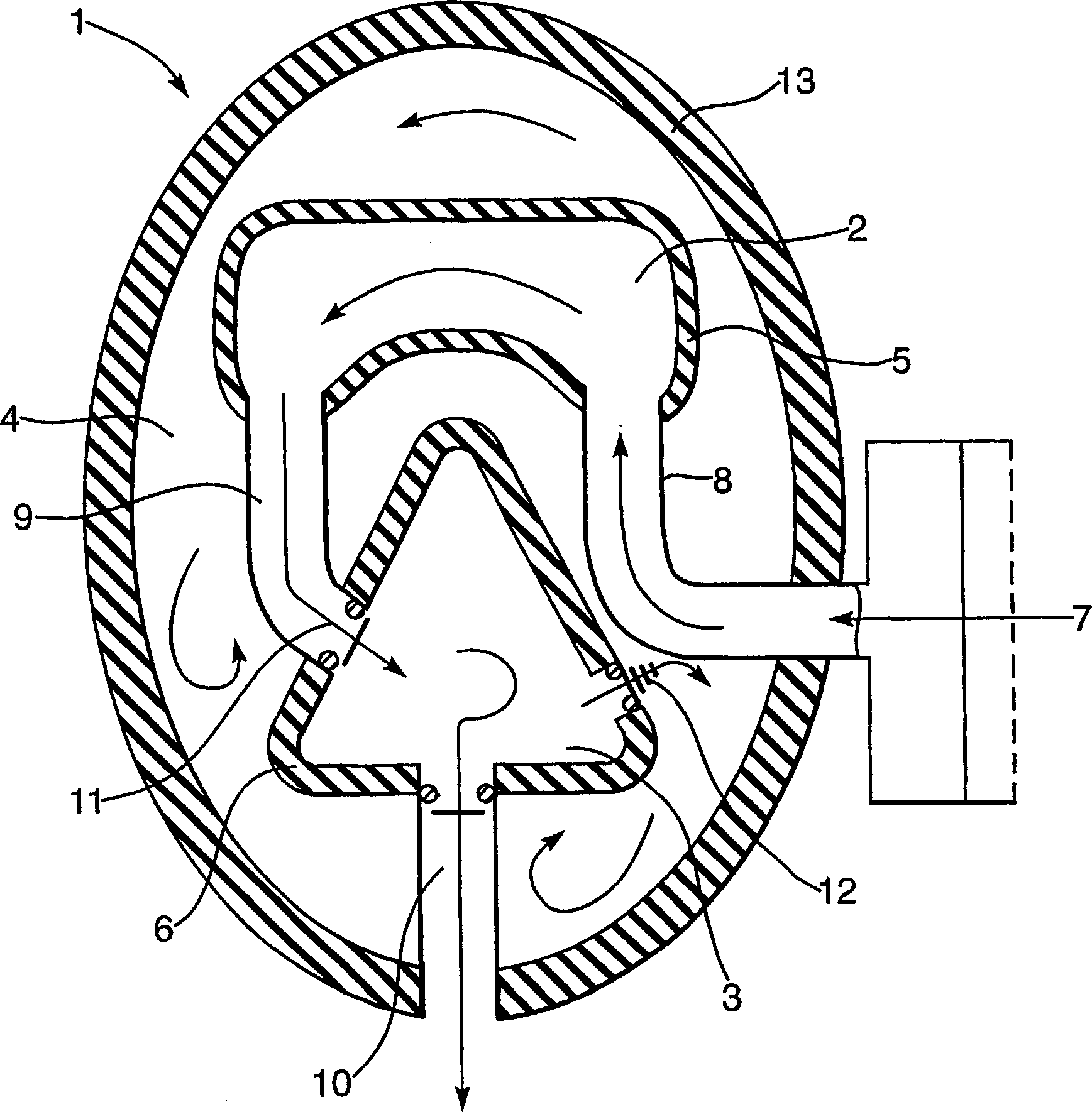
[0022] see figure 1 , the respirator 1 comprises in its body two separate inner masks 2, 3 forming a mask cavity 4 inside the outer mask. Both the eye mask 2 and the oronasal mask 3 have seals 5, 6 respectively, ensuring a tight and substantially airtight fit with the wearer. Inspiratory air is drawn in from the outside 7 through ducts 8 , 9 and flows through the eye mask 2 before being drawn into the oronasal mask 3 . The exhaled air is exhausted to the outside 7 through the valve 10 . The eyepiece of the eyepiece forms the eyepiece of the respirator, and the outer shield is sealed around the periphery of the eyepiece.

[0023] The inlet conduit 9 leading to the oronasal mask is provided with a one-way valve 11 and a second valve 12, which is spring-loaded so that it opens after the main valve 10 is opened and closes before the main valve closes, i.e. , which turns on during the time frame of the expiratory portion of the breathing cycle. This second valve 12 allows exhal...


PUM


Abstract

A respirator ( 1 ) having a plurality of internal masks ( 2, 3 ) within an external mask ( 4 ), the inner masks ( 2, 3 ) being linked by ducts ( 8, 9 ) so as to direct the inhaled air from the outside of the mask to the oronasal area via an ocular mask. The oronasal mask ( 3 ) has a secondary valve ( 12 ) that is sprung so as to operate within the timeframe of the exhalation part of the breathing cycle, the exhaled air being ejected into the hollow outer body of the mask ( 4 ).

Description

technical field [0001] The present invention relates to respirators and provides a respirator with a different inner facepiece to give additional protection to the wearer, the respirator is designed to use inhaled and exhaled air to increase the effectiveness of the respirator. Background technique [0002] Respirators allow workers to work in hazardous environments with airborne contaminants, and respirators typically rely on the wearer's exhaled air to create a positive pressure inside the mask. Thus, if any leaks occur where the mask forms a seal with the wearer's head, or if the seal of the mask is breached, exhaled air will flow out of the mask, thereby purifying the mask and carrying away any contaminated ambient air. [0003] However, upon inhalation, the pressure in conventional respirators drops below ambient so that inward leaks can occur allowing contaminants to enter the interior of the mask. Any contaminants inside the mask can cause injury or discomfort to the...

Claims


Application Information

Patent Timeline
IPC IPC(8): A62B18/04A62B18/02
CPCA62B18/02
Inventor 克里斯多弗·罗德尼·比
Owner THE SEC OF STATE FOR DEFENCE IN HER BRITANNIC MAJESTYS GOVERNMENT OF THE UK OF GREAT BRITAIN & NORTHERN IRELAND
Learn More