
Optical unit and a projection image display apparatus using the same

An image display device and optical image technology, which is applied in optical components, optics, projection devices, etc., can solve problems such as insufficient correspondence, and achieve the effects of suppressing production costs, high performance ratio, and high definition

Inactive Publication Date: 2005-07-13
HITACHI LTD
View PDF5 Cites 3 Cited by
  • Summary
  • Abstract
  • Description
  • Claims
  • Application Information

AI Technical Summary

Problems solved by technology

[0011] As mentioned above, in order to correct the astigmatism caused by the above-mentioned flat polarization separation mechanism, the methods described in the above-mentioned JP-A-5-313119, JP-9-114021, and JP-A-2000-111862 Astigmatism correction technology for chromatic mirrors cannot fully support

Method used


Image

  • Optical unit and a projection image display apparatus using the same
  • Optical unit and a projection image display apparatus using the same
  • Optical unit and a projection image display apparatus using the same

Examples


Embodiment Construction

[0029] Preferred modes for implementing the present invention will be described below with reference to the drawings.

[0030] figure 1 and figure 2 It is an explanatory diagram of the structure and function of main parts of the present invention. and, Figure 10 It is a diagram of a configuration example of a liquid crystal projector device as an embodiment of the projection type image display device of the present invention. In addition, the same code|symbol is attached|subjected to the part which has a common function in each figure.

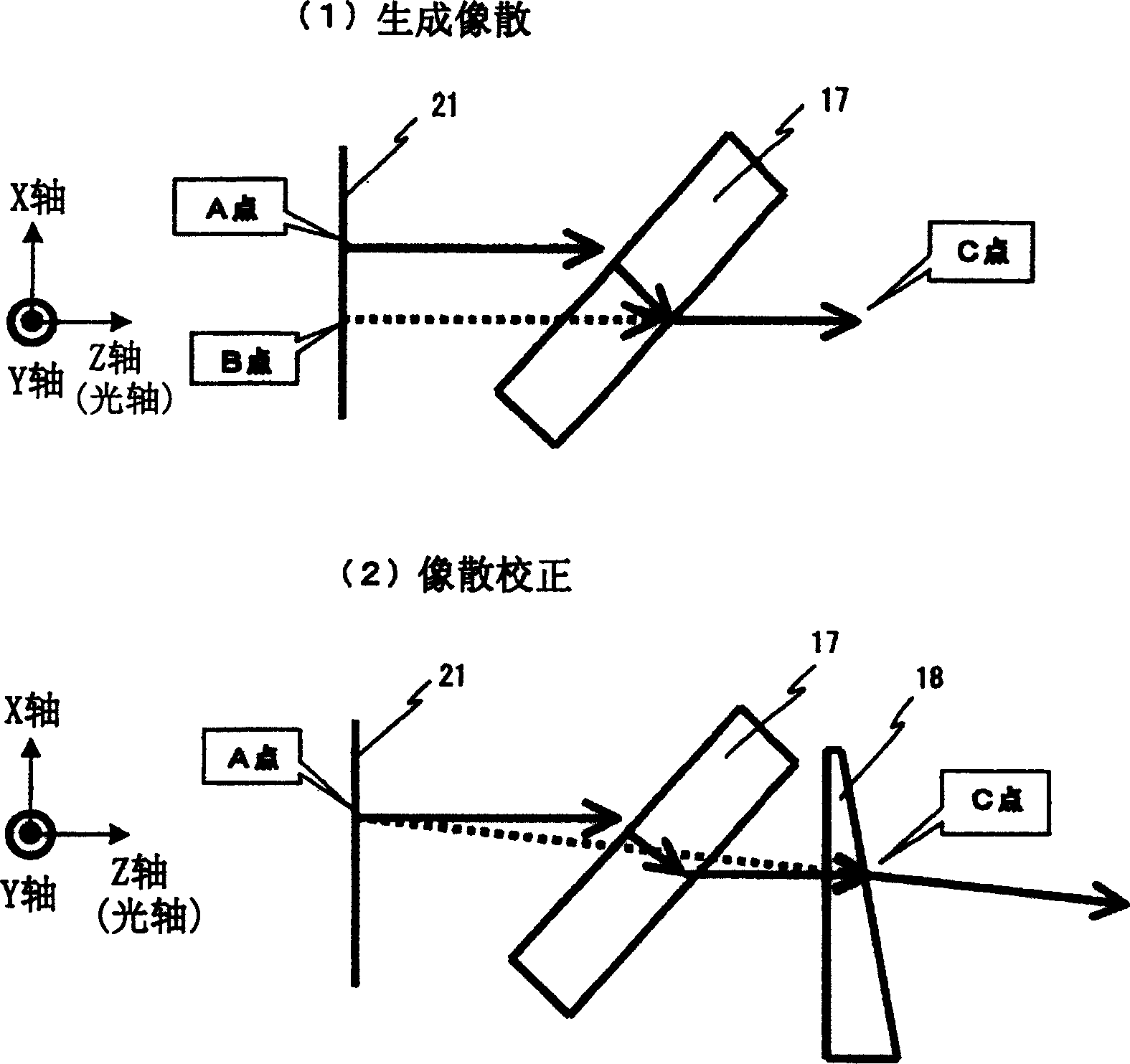
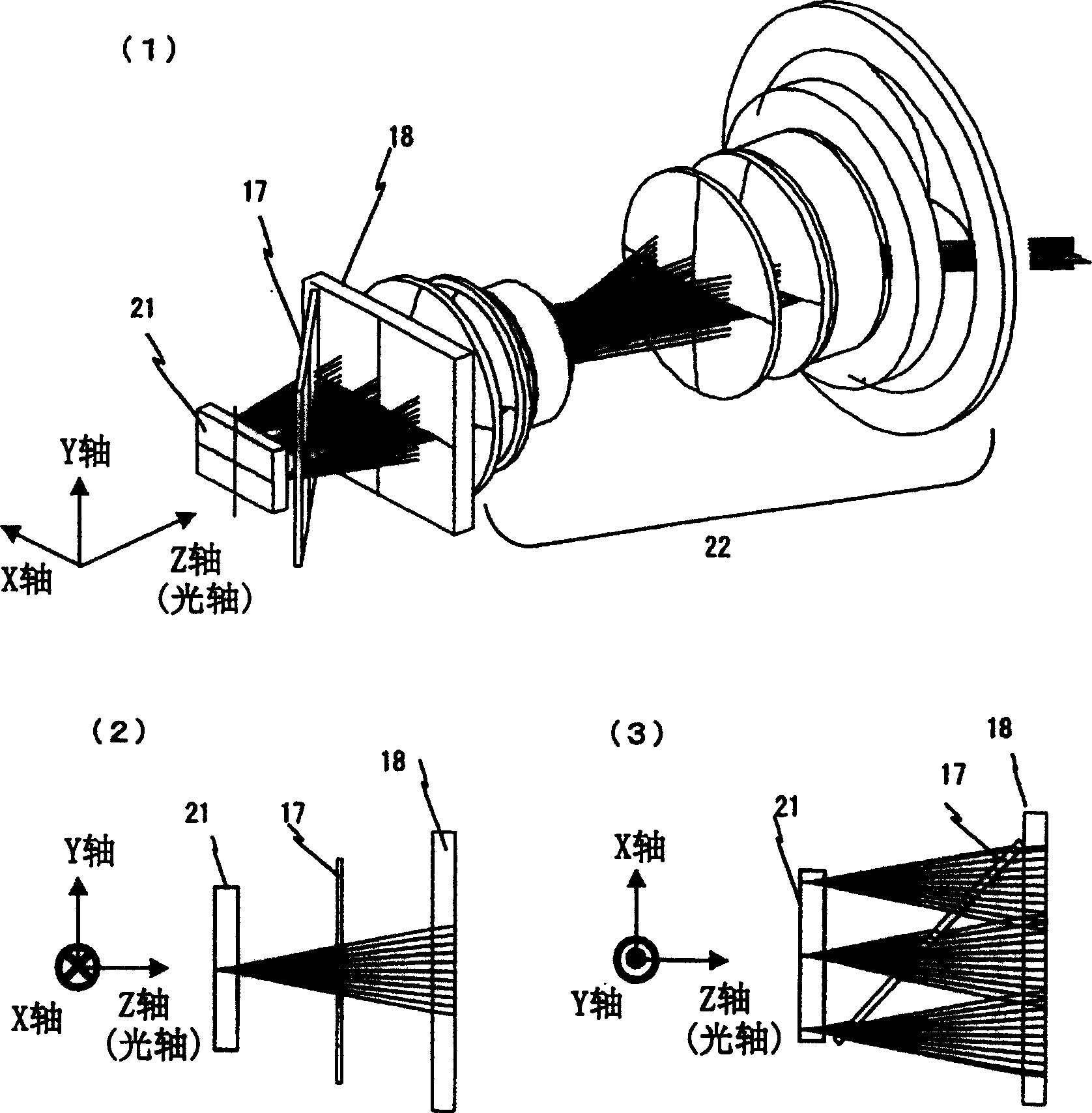
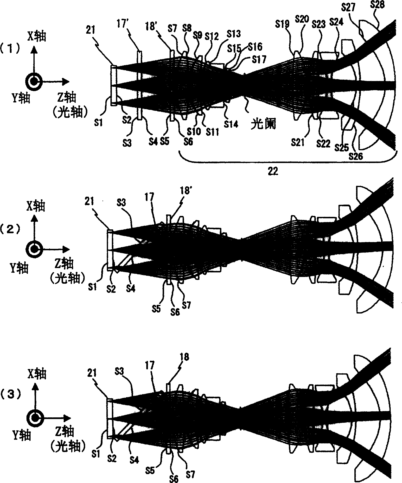
[0031] figure 1 It is a schematic diagram showing the structure of main parts in which a wire-grid type polarization separation element is obliquely arranged as a polarization separation mechanism mounted on a plate. figure 2 show figure 1 The main part of the light. figure 2 (1) is a perspective view of the same wire grid type polarization separation element arranged obliquely. figure 2 (2) is a YZ sectional view, figure 2 (...


PUM


Abstract

An element with a planar structure such as a wire grid polarization separation element is used as a polarization separation mechanism, and an astigmatism correction mechanism such as a cylindrical lens is provided between the polarization separation mechanism and a projection lens unit, thereby providing a projection-type image display device Among them, the technology that corrects the astigmatism caused by the polarization separation mechanism can ensure the sharpness of the projected image.

Description

technical field [0001] The present invention relates to an astigmatism correction technology for a projection type image display device that irradiates light from a light source side to a light valve such as a liquid crystal panel, forms an optical image corresponding to an image signal, and enlarges and projects it. Background technique [0002] In the prior art related to the present invention, as a polarization separation technique, for example, it is described in JP-A-2001-56449 and JP-A-10-55037, and as an astigmatism correction technique, for example, in JP-A-2001-55037. 5-313119 communiqué, Japanese Patent Application Laid-Open No. 9-114021, and Japanese Patent Laid-Open No. 2000-111862. [0003] In JP-A-2001-56449 and JP-A-10-55037, reflective light valves and polarization separation mechanisms for disposing 3 sets of red (R) green (G) blue (B) light are described; R, G , The color light of B is synthesized by the crossed dichroic prism. As the polarization splitti...

Claims


Application Information

Patent Timeline
Patent Type & Authority Applications(China)
IPC IPC(8): G02B5/30G02B13/16G02B27/00G02B27/18G02F1/13G02F1/1335G03B21/00
CPCG02B13/16G02B27/0025
Inventor 谷津雅彦中岛努
Owner HITACHI LTD
Learn More