Photographic trick makig device

A technology for making devices and special effects, which is applied in the directions of printing devices, optics, instruments, etc., to achieve the effects of low price, fast production and simple production method

Inactive Publication Date: 2005-07-13
叶建华
View PDF0 Cites 0 Cited by
  • Summary
  • Abstract
  • Description
  • Claims
  • Application Information

AI Technical Summary

Problems solved by technology

Computer image processing can produce artistic effects that cannot be achieved in traditional darkroom production. However, there is a qualitative dif...

Method used


Image

  • Photographic trick makig device
  • Photographic trick makig device

Examples


Embodiment Construction

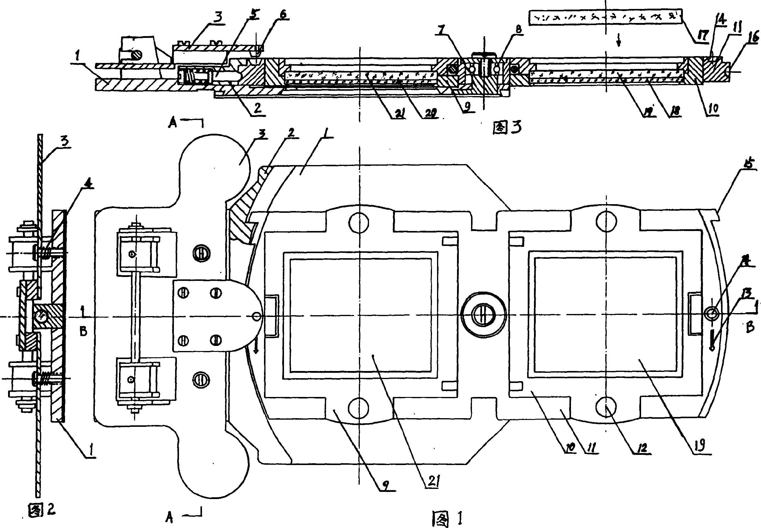
[0036] This embodiment is applicable to the Japan Noritshi QSS-1201 (1202.1700 etc.) color enlarging machine.

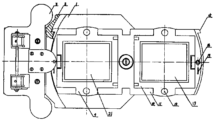
[0037] As shown in Figures 1 to 3, a photographic special effects production device, a base 1 is provided with a turret 11 on one side, and the turret 11 can rotate 180 degrees clockwise or counterclockwise. Only the same film holder 9 and 10 of structure, a piece of holder 9 is equipped with pictorial negative film 20 and positive mask 21, and another sheet holder 10 is equipped with portrait negative film 18 and negative mask 19 or filter filter 17.

[0038] Positive mask 21 and negative mask 19 are made of optical glass, and can also be made of printing plates.

[0039] As shown in FIGS. 1 and 3 , a suction plate 3 is provided on the other side of the base 1 , and a positioning pin 6 is provided under the suction plate 3 .

[0040] As shown in Figures 1 and 2, the bomb-absorbing end of the suction plate 3 is installed on the base 1 with two screws, and the spring...


PUM


Abstract

The photographic trick making device includes one base seat, one rotating frame capable of rotating clockwise or counterclockwise by 180 deg, and two film holders set on the rotating frame. Of these two film holders, one holds picture negative and positive masking film, and the other holds portrait negative and negative masking film or filter lens. The present invention is used in color enlarging and printing machine, opening cutting enlarger, etc. for increasing trick making function. The photographic trick making device can meet the requirement of commercial photographic equipment in making speed, quality, cost and size.

Description

1. Technical field [0001] The invention relates to the technical field of photo production, in particular to a photographic special effect production device. 2. Background technology [0002] Creative special effects production has always been an enthusiastic project for photographers, darkroom production technicians and photography hobbyists. They have created a large number of excellent works and compiled many theoretical works on special effects production in the darkroom. However, for many years, no matter how hard photographers and darkroom production technicians work, the photos produced can only be a single photographic art work, which cannot be commercially applied in the photography industry and cannot directly serve the public. Trace it to its cause and be: do not have special-purpose production device. It is time-consuming to make by hand in the darkroom, the success rate is low, and skilled production techniques are required. Today's color photo printers and b...

Claims


Application Information

Patent Timeline
IPC IPC(8): G03B17/54G03B27/52
Inventor 叶建华
Owner 叶建华
Why Eureka
Try Eureka