Band-steel laminar-flow cooling device and its cooling control method

A laminar flow cooling device and controlled cooling technology, applied in metal rolling, manufacturing tools, metal rolling, etc., can solve the problems of difficult control of cooling rate, unreasonable header structure, poor temperature control accuracy, etc., and achieve improved The effect of cooling control precision, complex combination, and strong cooling capacity

Inactive Publication Date: 2005-07-20
ANGANG STEEL CO LTD
View PDF0 Cites 46 Cited by
  • Summary
  • Abstract
  • Description
  • Claims
  • Application Information

AI Technical Summary

Problems solved by technology

Since the length of the cooling zone of this cooling device is relatively short, generally 20-80m, and the structure of the header is not reasonable, this cooling method can only form a simple cooling method of main cooling + fine-tuning for simple coiling Temperature control, it is difficult to achieve co

Method used


Image

  • Band-steel laminar-flow cooling device and its cooling control method
  • Band-steel laminar-flow cooling device and its cooling control method
  • Band-steel laminar-flow cooling device and its cooling control method

Examples


Embodiment Construction

[0011] The strip laminar flow cooling device and its control cooling method of the present invention will be further described below with reference to the accompanying drawings.

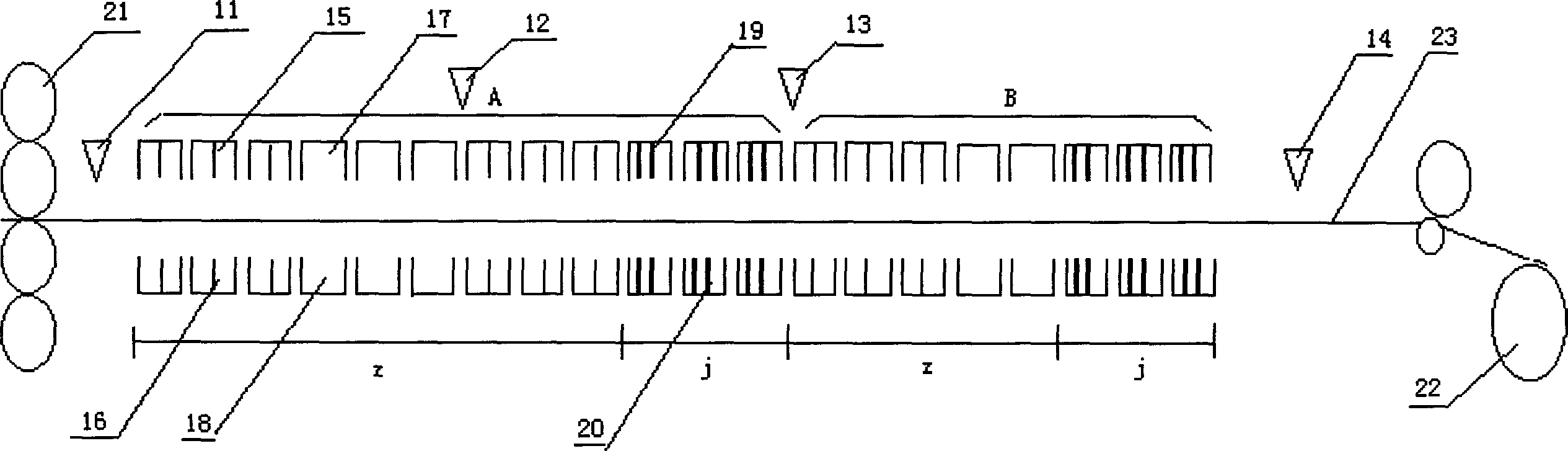
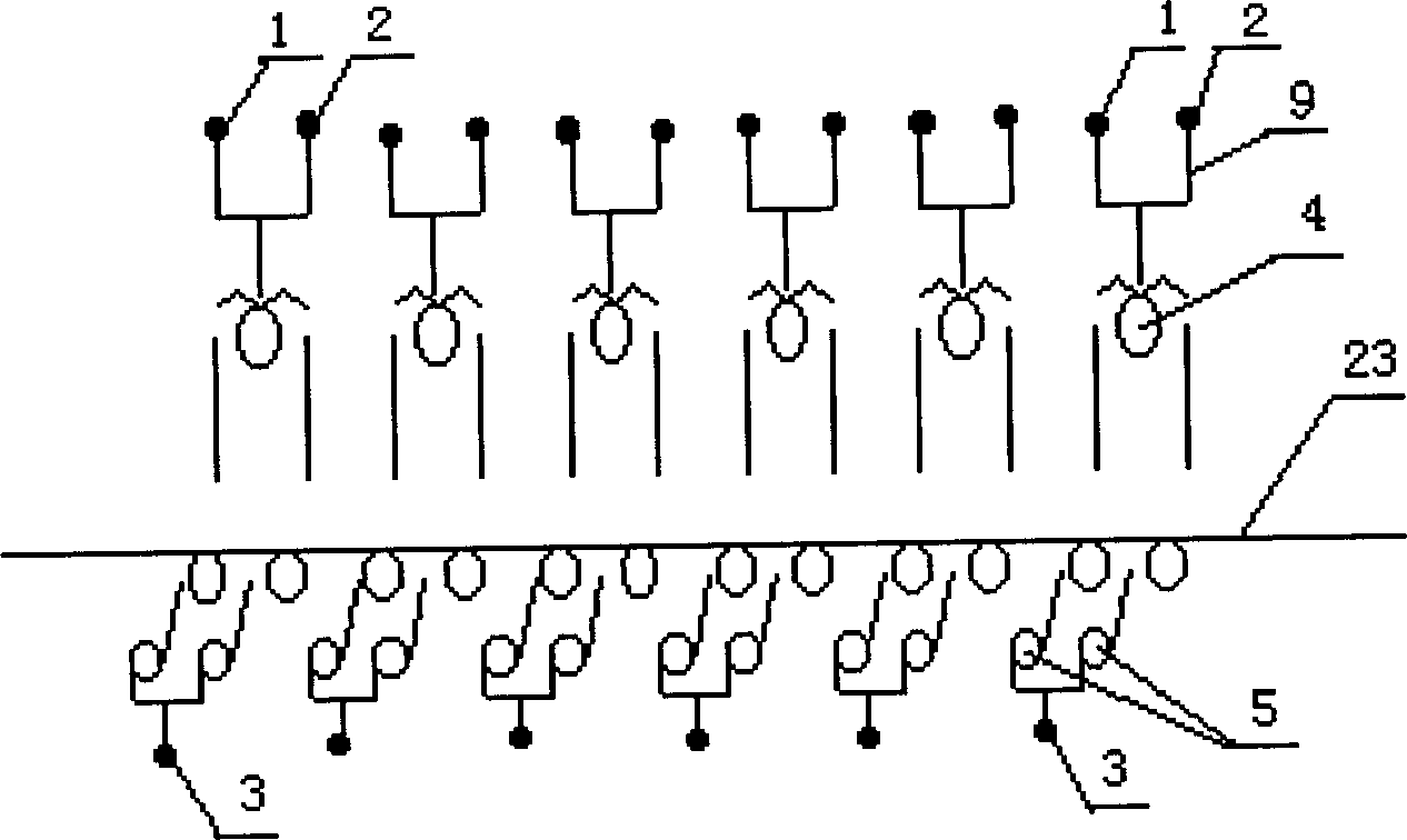
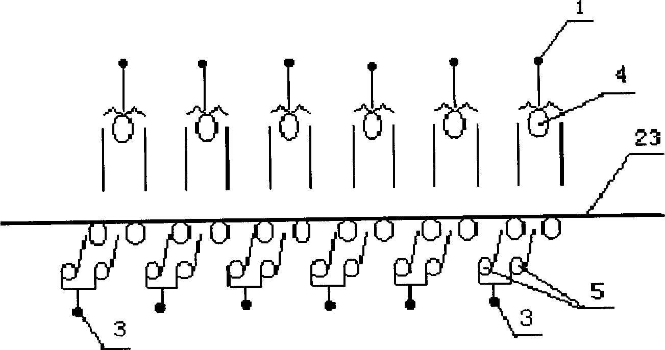
[0012] The strip steel laminar flow cooling device of the present invention is mainly composed of a cooling zone composed of several upper laminar flow header groups and a corresponding number of lower spray header groups, and is the same as the existing laminar flow cooling device. The side is provided with a side blowing mechanism along the length of the cooling zone. attached figure 1 It is a specific embodiment of the present invention. 23 is strip steel among the figure. It can be seen from the drawings that the cooling device is composed of two cooling zones with their own main cooling section Z and finishing cooling section J, that is, the front cooling zone A and the rear cooling zone B are connected in series, and its structural form is : main cooling section Z + finishing cooling section...


PUM


Abstract

The present invention provides a strip steel laminar flow cooling device which has two cooling zones and has strong cooling function and its controlled cooling method. Said device is formed from cooling zone consisting of upper laminar flow manifold and lower jet manifold, and said cooling zone includes two portions of main cooling section and fine cooling section which are formed from several upper laminar flow manifold groups and correspondent number of lower jet manifold groups. Its controlled cooling method is implemented by using computer to make setting computation, feedback computation and feedforward computation.

Description

technical field [0001] The invention belongs to strip steel cooling technology, in particular to a laminar flow cooling device for hot-rolled strip steel and a control cooling method thereof. Background technique [0002] In the production process of hot-rolled strip steel, in order to further improve product quality and increase economic benefits, and obtain high-quality mechanical properties of hot-rolled strip steel, after the hot-rolled strip steel leaves the last stand finishing mill and before entering the coiler, it needs to The hot-rolled strip is cooled to control the cooling rate and coiling temperature of the strip to obtain the desired structure and properties. At present, the entire cooling area of ​​the laminar flow cooling system of the hot-rolled strip steel production line is mainly composed of the upper laminar flow header and the lower injection header. There is also a side blowing mechanism along the length of the cooling area. The entire cooling area is ...

Claims


Application Information

Patent Timeline
IPC IPC(8): B21B45/02
Inventor 沙孝春李龙珍孙大庆关菊那杰夫扬旭吴晓伟张丽芬
Owner ANGANG STEEL CO LTD
Why Eureka
Try Eureka