Lamp body structure for reflecting device and its manufacturing method

A technology of a reflective device and a manufacturing method, which is applied to identification devices, instruments, etc., can solve the problems of difficult quality control, complicated manufacturing operations, uneven quality, etc., and achieve the effect of improving economic efficiency and changing manufacturing and structure methods.

Inactive Publication Date: 2005-07-20
HAYASHIBARA CO LTD
View PDF0 Cites 2 Cited by
  • Summary
  • Abstract
  • Description
  • Claims
  • Application Information

AI Technical Summary

Problems solved by technology

However, the structural design of the above-mentioned reflective devices cannot be used to integrate the lamp body and the reflective light because it needs to assemble the lamp body and the electric wire and then place it in the reflective strip. The strips are modularized and assembled respectively, so the production and assembly speed are slow, and it is difficult to have high industrial production efficiency; moreover, because most of the lamp bodies in the reflective strip have a certain distance, but because of the implementation of the object (clothes or Related objects) have different sizes and styles. For example, the reflective tape on the clothes has special parts such as shoulder straps and belts. In actual production, the manufacturer must have a variety of reflective tapes with different lamp body spacing and different lengths. The demand for supplying a small amount of diverse production leads to meager profits or the control of hoarding and stocking objects, and may even lead to uneven quality in response to diversified needs; moreover, the above-mentioned commonly used reflective tapes require additional waterproof treatment, not only The manufacturing operation is complicated, and the quality control is also relatively difficult. Once it needs to be used in places with high safety standards (such as places with gas or gas explosions), if the airtightness is slightly flawed, the lamp body, wires and flickering Micro-currents such as controllers have disadvantages such as the risk of gas explosions; therefore, how to solve the problems of production efficiency and safety of reflective tapes is a key direction for the industry to make further breakthroughs and improvements.
[0003] In view of the above-mentioned shortcomings of poor production efficiency of the reflective tape and the fact that its structural safety design is not very ideal, the inventor started to develop its solution, hoping to develop a reflective tape with more industrial manufacturing benefits, high efficiency and safety For industrial use, the present invention has been produced after a long time of thinking

Method used


Image

  • Lamp body structure for reflecting device and its manufacturing method
  • Lamp body structure for reflecting device and its manufacturing method
  • Lamp body structure for reflecting device and its manufacturing method

Examples


no. 1 example

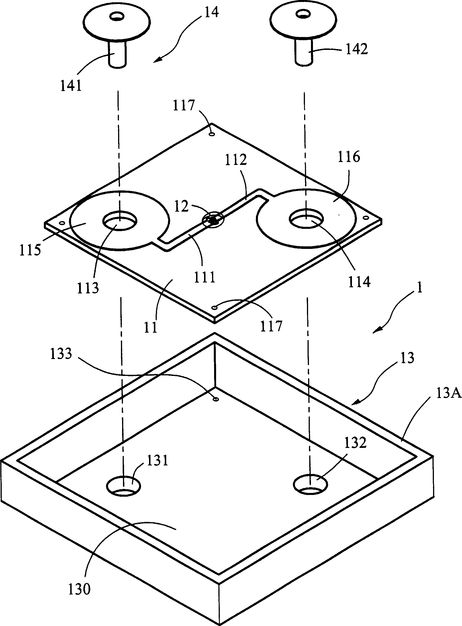
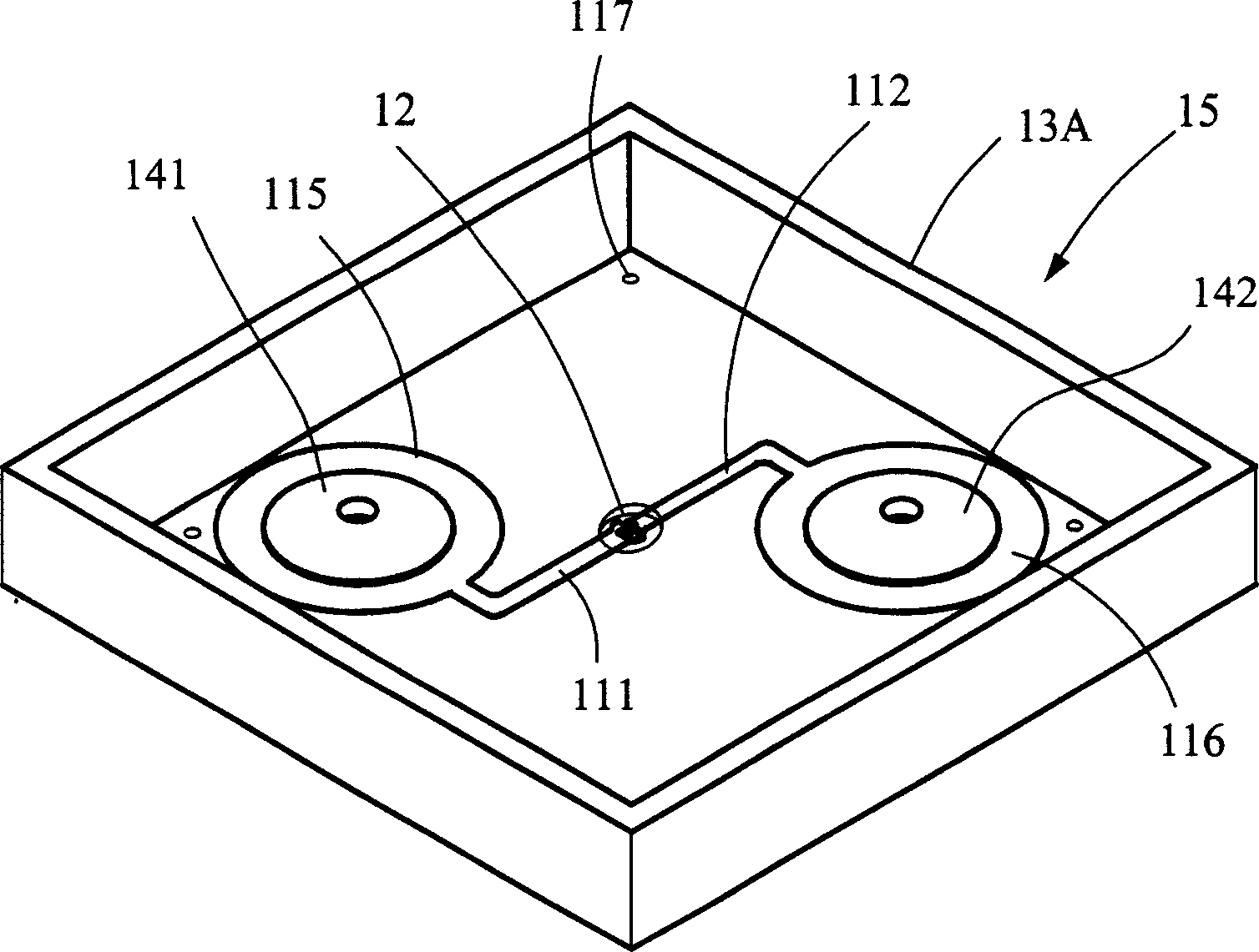
[0109] Please refer to FIG. 21 , which is the first embodiment of the heat-press packaging manufacturing method of the lamp body unit 1 of the present invention. The substrate 11 , the LED lamp group 12 and the rivet group 14 are assembled and fixed on the base 13A to form the base unit. 15 (the base units 15A, 15B are the same), then the base 13A is covered with a cover plate 19, and the side of the cover plate 19 opposite to the base 13A is provided with a plurality of abutment posts 191 for the base. 13A produces a supporting effect. When the sealing plate 19 is covered on the base 13A, it is welded and fixed by a high-frequency or ultrasonic welding machine, so that the sealing plate 19 and the base 13A are fused together to form a protruding rivet The lamp body unit 1 of 141, 142, such as Figure 22 shown.

[0110] another example Figure 23 , 24, the accommodating space 130 of the base 13A is provided with a pair of grooved positioning columns 138 for inserting and pos...


PUM


Abstract

The invention provides a lamp body of the light-reflectance apparatus and its manufacture method. It comprises that a base plate, it is set complex number through holes; a LED lamp bank, it is set on the base plate; a base seat, it has space, and complex number fixed holes are set in it; a rivet set, it comprises complex number rivets, the rivet is drilled through the through hole and the fixed hole, and fixedly welded on the former, and it realizes electrical property connection with the LED lamp bank; a filling rubber, it is filled in the space of the base seat. This can make the lamp body of the light-reflectance apparatus has the modularization design. Thus, the manufacture and assemble of the light-reflectance apparatus have the better economic benefit.

Description

technical field [0001] The present invention relates to a lamp body device, in particular, to a lamp body structure and a manufacturing method of a reflector device that can be conveniently assembled and applied to a reflector device, and can provide a safety reflective signal. Background technique [0002] The commonly used reflective tape (reflective device) is made of multiple lamp bodies connected in parallel with electric wires, then connected with switches, power supplies or batteries and flashing controllers, and put into a reflective tape or waterproof tape, and finally put It is sewed on clothes or related objects, and related technologies have bulletin No. 355642, No. 383121, etc. However, the structural design of the above-mentioned reflective devices cannot be used to integrate the lamp body and the reflective light because it needs to assemble the lamp body and the electric wire and then place it in the reflective strip. The strips are modularized and assembled...

Claims


Application Information

Patent Timeline
IPC IPC(8): G09F9/33
Inventor 林原
Owner HAYASHIBARA CO LTD
Why Eureka
Try Eureka