Control for pipeline gas distribution system

A distribution system, management and control technology, applied in the direction of electric fluid pressure control, fluid pressure control, flow control, etc., can solve expensive and other problems

Inactive Publication Date: 2005-07-27
PRAXAIR TECH INC
View PDF0 Cites 7 Cited by
  • Summary
  • Abstract
  • Description
  • Claims
  • Application Information

AI Technical Summary

Problems solved by technology

However, as liquid oxygen is a more expensive product to produce than gas

Method used


Image

  • Control for pipeline gas distribution system
  • Control for pipeline gas distribution system
  • Control for pipeline gas distribution system

Examples


Embodiment Construction

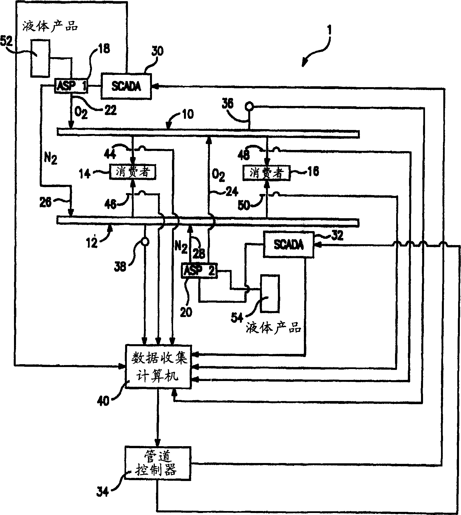
[0026] refer to figure 1 , illustrates a gas distribution system 1 controlled according to the present invention. It should be understood that the gas distribution system 1 is illustrated for exemplary purposes and that the system to be controlled in accordance with the invention may be more complex or simpler than that illustrated.

[0027] The gas distribution system 1 comprises pipeline sections 10 and 12 supplying gaseous oxygen and gaseous nitrogen to consumers 14 and 16, respectively. Piping sections 10 and 12 are supplied with gaseous oxygen and nitrogen by air separation plants ( ASP1 and ASP2 ) 18 and 20 . Air separation plants 18 and 20 are connected to pipeline sections 10 and 12 by oxygen conduits 22 and 24 and nitrogen conduits 26 and 28 . In this regard, the purity of the supplied oxygen and nitrogen depends on the type of air separation plant used to meet the needs of consumers 14 and 16 .

[0028]Air separation units 18 and 20 separate oxygen and nitrogen fr...


PUM


Abstract

A method of controlling a gas distribution system in which one or more air separation plants supply gaseous oxygen and nitrogen products to pipeline sections. The air separation plants are controlled by supervisory control systems that direct production rates of the gaseous products to be consumed by customers connected to the pipeline sections. The gas distribution system is controlled by a model predictive control system in which empirically determined open loop response models are used to generate open loop responses of the pipeline sections due to changes in customer demands. Optimized closed loop responses in production rate requests to the supervisory control systems are generated by model predictive control techniques.

Description

field of invention [0001] The present invention relates to a method of controlling a gas distribution system comprising one or more piping sections supplied with gaseous oxygen and / or nitrogen from an air separation plant and, in particular, the present invention relates to a method wherein a model predictive controller The supply of gaseous oxygen and / or nitrogen to the air separation plant is controlled in response to pipeline pressure and customer demand. Background of the invention [0002] The gas distribution system includes an air separation plant which produces gaseous oxygen and gaseous nitrogen products by cryogenic distillation of air by well known techniques. These products are supplied to consumers by a pipeline comprising one or more parts. This gas distribution system is manually controlled by the supplier to ensure that each part of the pipeline is above a certain minimum pressure agreed by the customer. The pressure in the pipeline se...

Claims


Application Information

Patent Timeline
IPC IPC(8): G05D16/20
CPCG05D16/20Y10T137/268
Inventor L·梅甘D·F·伦诺克斯P·F·沙夫D·阿德贝昆M·朱
Owner PRAXAIR TECH INC
Why Eureka
Try Eureka