
Claw-pole type generator

A generator and claw pole type technology, applied in the field of claw pole type generators for bicycles, to achieve the effect of reducing assembly cost and being easy to handle

Inactive Publication Date: 2005-07-27
ICHINOMIYA ELECTRIC
View PDF4 Cites 8 Cited by
  • Summary
  • Abstract
  • Description
  • Claims
  • Application Information

AI Technical Summary

Problems solved by technology

But when the core yoke 92 is constructed by combining the divided pieces 93 having a constant shape into a square cylindrical shape as shown in the figure, a problem is that there are many spaces where the thin plate 93a is not provided at the center of the coil 94.

Method used


Image

  • Claw-pole type generator
  • Claw-pole type generator
  • Claw-pole type generator

Examples


Embodiment Construction

[0036] Hereinafter, embodiments of the present invention will be described with reference to the drawings.

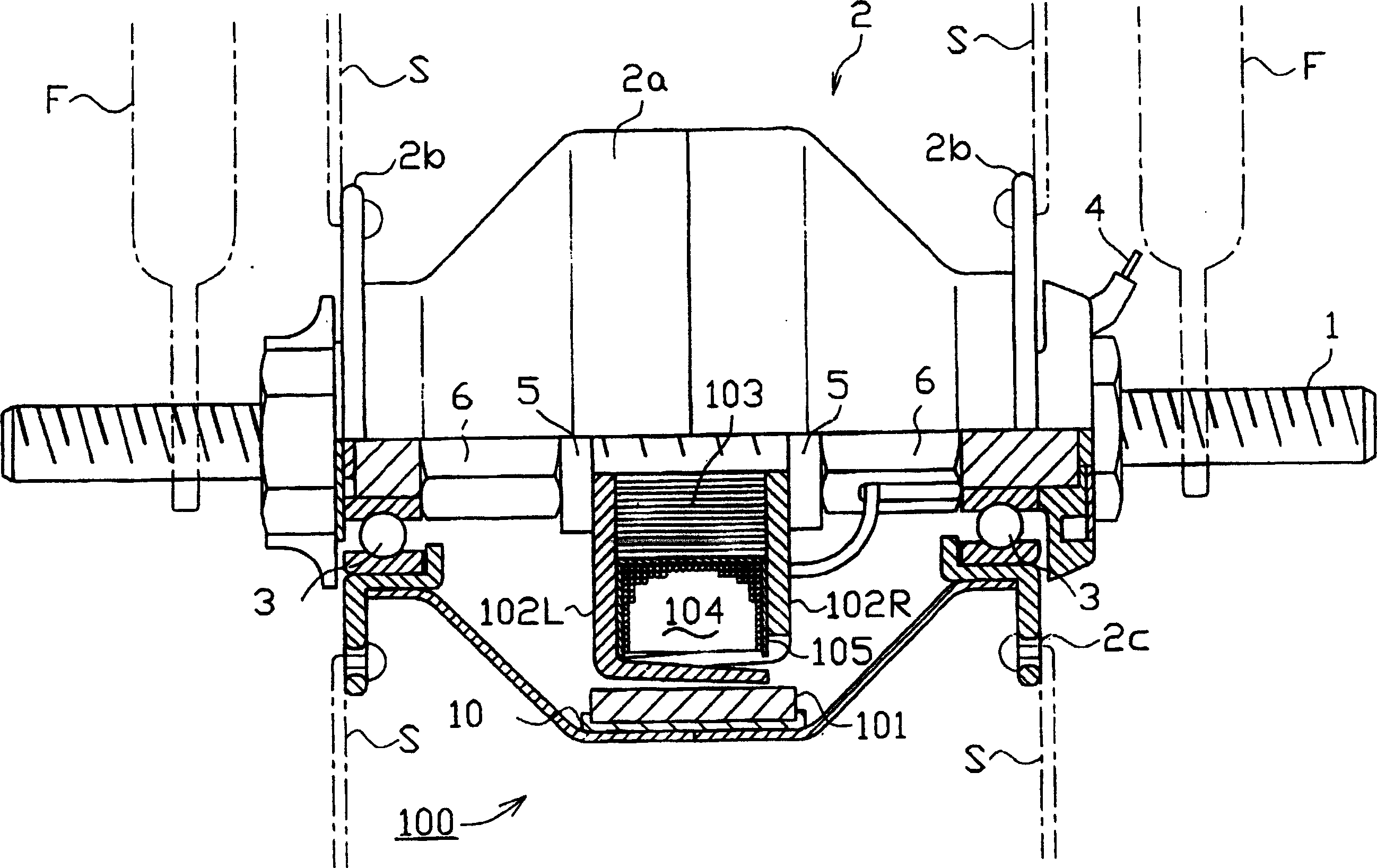
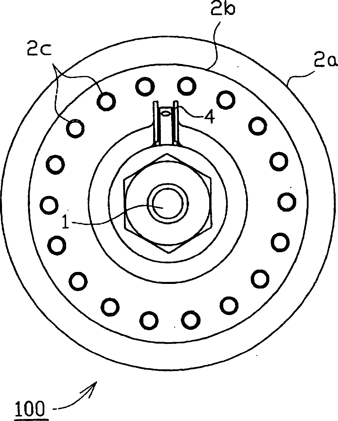
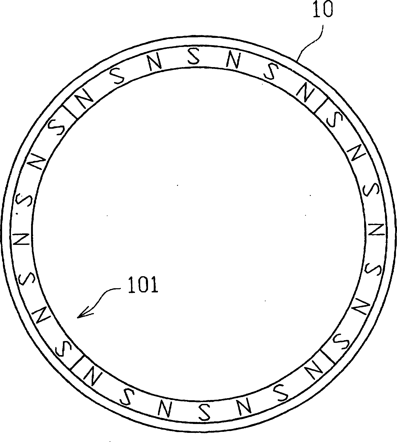
[0037] figure 1 The overall configuration of a claw pole generator 100 according to an embodiment of the present invention is shown. Such as figure 1 As shown, the claw pole generator 100 has a ring-shaped permanent magnet 101, two stator yokes 102L and 102R arranged opposite to the permanent magnet 101, a core yoke 103 magnetically connecting the stator yokes 102L and 102R, and a A coil 104 is provided around the core yoke 103 . The thus constituted claw pole generator 100 is fixed to a hub shaft 1 of any known bicycle wheel, and the claw pole generator 100 constitutes a bicycle hub generator. In addition, a male thread / external thread is formed on the hub shaft 1, and the hub shaft 1 is fixed to a fork F for a bicycle wheel by a nut or the like.

[0038] A hub cover 2 is rotatably connected to the hub shaft 1 via a bearing 3 . The hub cap 2 has a drum hub 2a an...


PUM


Abstract

A claw-pole type generator (100) comprising a permanent magnet (101), two stator yokes (102L, 102R), a core yoke (103), and a coil (104), wherein the core yoke (103) comprises a pair of first semicylindrical split pieces (30) formed by stacking a plurality of thin plate materials (30a-30m), and a pair of second prismatic split pieces (31) formed by stacking a plurality of thin plate materials (31a-31m). Each thin plate material of the first split piece (30) and each thin plate material of the second split piece (31) intersect perpendicularly, the first split pieces (30) face each other and the second split pieces (31) face each other across the axis and the second split pieces (31) are pinched by the first split pieces (30) and combined substantially cylindrically.

Description

technical field [0001] The invention relates to a claw pole generator, in particular to a claw pole generator for bicycles. Background technique [0002] A conventional claw pole generator comprises a cylinder with a permanent magnet, two claw pole stator yokes respectively having pole pieces arranged alternately and in parallel in the circumferential direction, and an iron core yoke magnetically connecting the stator yokes (core yoke) and a coil around the core yoke. The claw pole generator includes permanent magnets as an outer rotor, a stator yoke as an inner stator, core yokes and coils. The rotation of the permanent magnet causes an alternating magnetic flux to be generated in the core yoke, so that a current flows through the coil to generate electricity. [0003] Since an eddy current is generated while alternating magnetic flux is generated in the stator yoke and the iron core yoke, the eddy current reduces power generation efficiency, and therefore it is necessary...

Claims


Application Information

Patent Timeline
Patent Type & Authority Applications(China)
IPC IPC(8): H02K1/18H02K1/14H02K15/02H02K19/22H02K21/22
CPCH02K1/145H02K21/22H02K15/022
Inventor 秋田卯市
Owner ICHINOMIYA ELECTRIC
Learn More