Broach cleaning device

A technology for cleaning devices and broaching machines, which is applied to broaching tools, accessories of broaching machine devices, broaching machines, etc., which can solve the problems of reduced ability to remove chips and incomplete removal of chips, and achieve effective chip removal and improved cleaning functions. Effect

Inactive Publication Date: 2005-08-03
FUJINON SANO
View PDF1 Cites 7 Cited by
  • Summary
  • Abstract
  • Description
  • Claims
  • Application Information

AI Technical Summary

Problems solved by technology

[0006] However, when the brush is rotated in one direction to rub the blade of the broach, chips are accumulated in one direction, and a part of the chips wiped off by the rotating brush may remain on the blade and remain on the blade. Sometimes the chips attached to the machine cannot be completely removed
And, in cleaning, because the brush is always bent in one direction, so there will be bending habit, and because of reasons such as brush wear and tear, the ability of the brush to remove chips from the blade is reduced. There is still room for improvement in terms of cleaning function, as well as in terms of brush life

Method used


Image

  • Broach cleaning device
  • Broach cleaning device
  • Broach cleaning device

Examples


Embodiment Construction

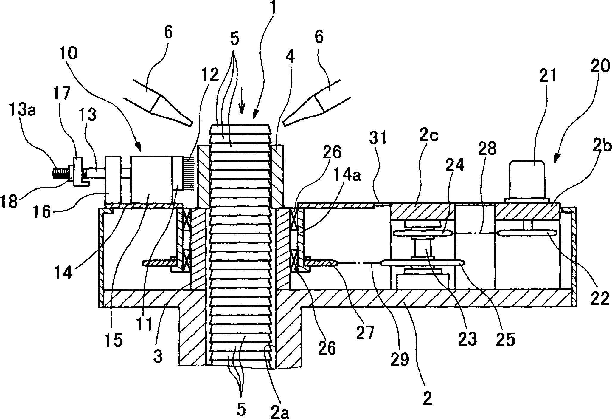
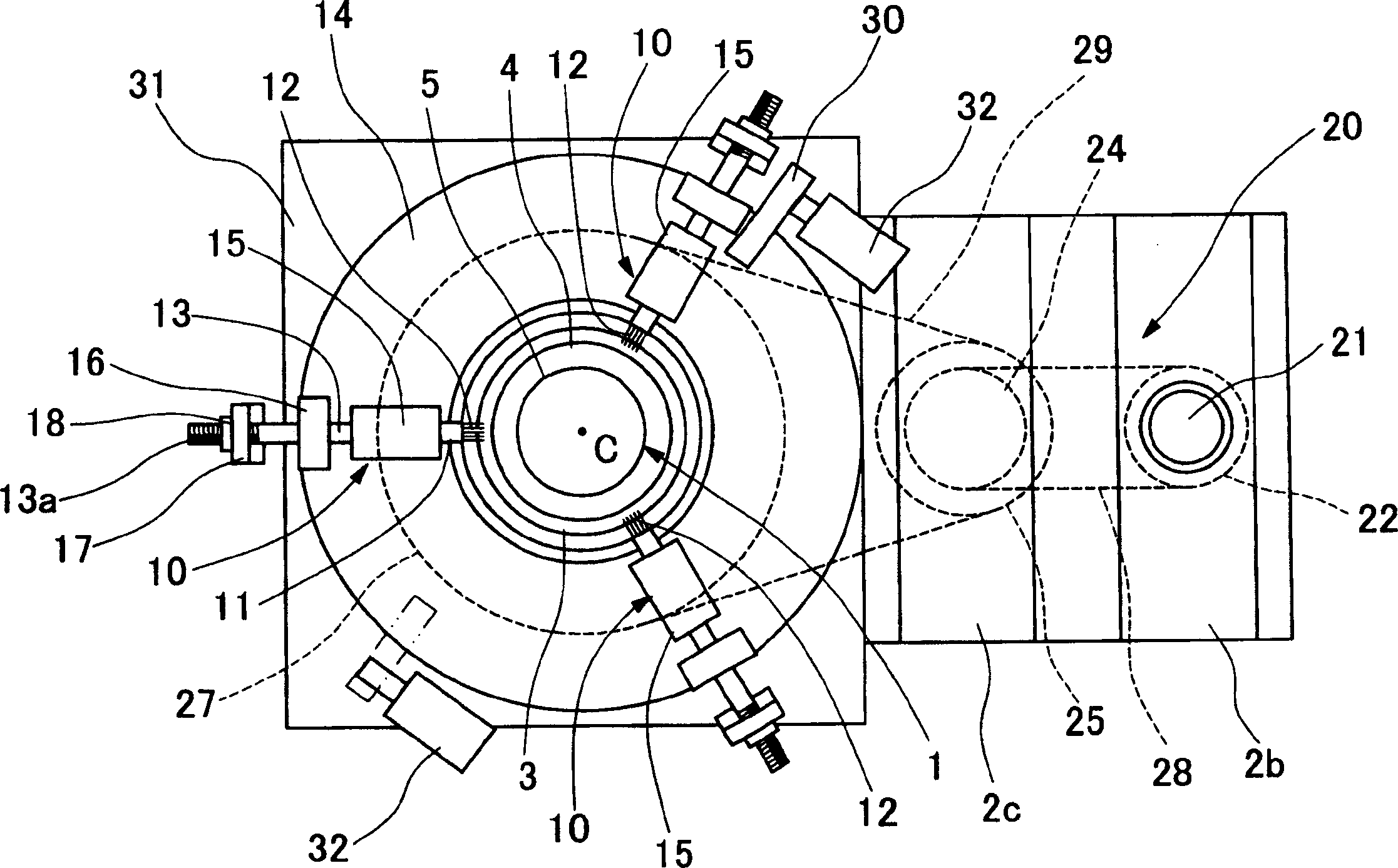
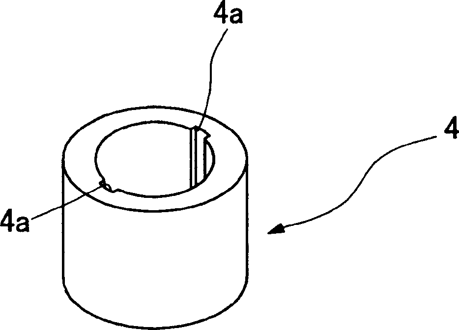
[0019] Embodiments of the present invention are described below with reference to the accompanying drawings. At first, figure 1 as well as figure 2 Indicates the structure of important parts of the broaching machine. In the figure, 1 is a broach, 2 is a support plate, and 3 is a mounting seat, for example image 3 The configuration shown is a portion of the broaching machine for forming a groove 4 a facing the axial direction on the inner surface of a cylindrically shaped workpiece 4 .

[0020] The drawing of the broach 1 is omitted, but its structure has upper and lower clamping parts, and a blade part 5 is provided between the two clamping parts, and is arranged so as to pass through the penetration hole 2a formed in the supporting table 2. . Such as Figure 4 As shown, the cutting edge portion 5 has annular cutting edges 5a facing the axial direction of the broach 1 and arranged at predetermined intervals, and a groove for machining the groove 4a of the workpiece 4 is ...


PUM


Abstract

To lengthen the service life, by improving the cleaning function of chips, by strongly rubbing a broach by a brush. This device is arranged in three places so that a brush unit 10 forms a concentric circle to the center C of the broach 1, and is constituted so as to be reciprocatably supported in the direction for approaching / separating to the center C of the broach 1 by a driving cylinder 15. This device is rubbed in the circumferential direction along a cutting edge part 5 of the broach 1 by reciprocatably rotating a turntable 14 in the horizontal direction by 180[deg.] in a state of putting the brush in an operation position, and brushes off and removes the chips sticking to a part over an inner surface part 5c from an edge part 5b of a cutting edge 5a for constituting the cutting edge part 5 in the broach 1.

Description

technical field [0001] The invention relates to a broach cleaning device for removing chips from broaches of a broaching machine. Background technique [0002] A broaching machine, a working machine that processes the inner surface of a circular workpiece to form grooves in the axial direction, has the following structure. On a table with a through hole, a workpiece is placed around the through hole. The broach is mounted on the mounting seat so as to be movable up and down through the through hole, wherein a plurality of cutting edge portions are formed on the outer peripheral portion of the broach toward the axial direction. Because the broaching tool cuts the workpiece, chips are generated during this machining. Therefore, if the swarf is not removed after the machining, the correct groove cannot be formed in the next machining, and the inner surface of the workpiece including the groove may be damaged due to the swarf, and defects such as burrs may be generated. Theref...

Claims


Application Information

Patent Timeline
Patent Type & Authority Applications(China)
IPC IPC(8): B23Q11/00B23D39/00B23D43/02
Inventor 田名网重昭
Owner FUJINON SANO
Why Eureka
Try Eureka