Back light module

A backlight module and backplane technology, applied in optics, electric light sources, nonlinear optics, etc., can solve the problems of unavailability, reduce complexity and cost, and achieve reduced usage, reduced complexity and cost, and stable combination Effects of complexity and cost

Active Publication Date: 2005-08-03
AU OPTRONICS CORP
View PDF0 Cites 8 Cited by
  • Summary
  • Abstract
  • Description
  • Claims
  • Application Information

AI Technical Summary

Problems solved by technology

[0005] In view of the above-mentioned prior art, the method used to fix the light-emitting unit in the backlight module in the prior art cannot provide a stable combination and reduce the complexity and cost of assembly. Therefore, a light-emitting unit is provid

Method used


Image

  • Back light module
  • Back light module
  • Back light module

Examples


Embodiment Construction

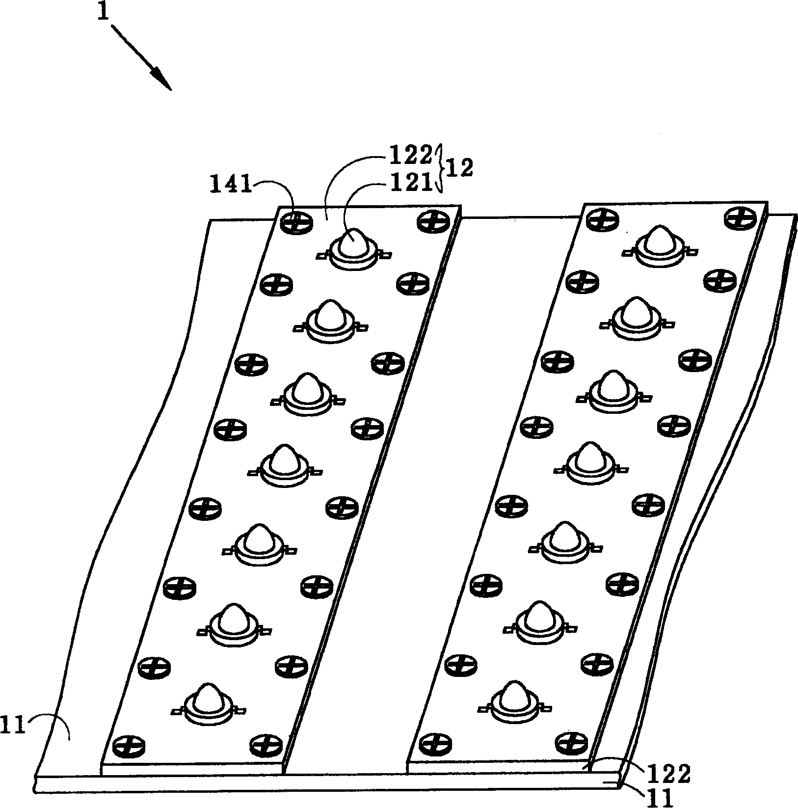
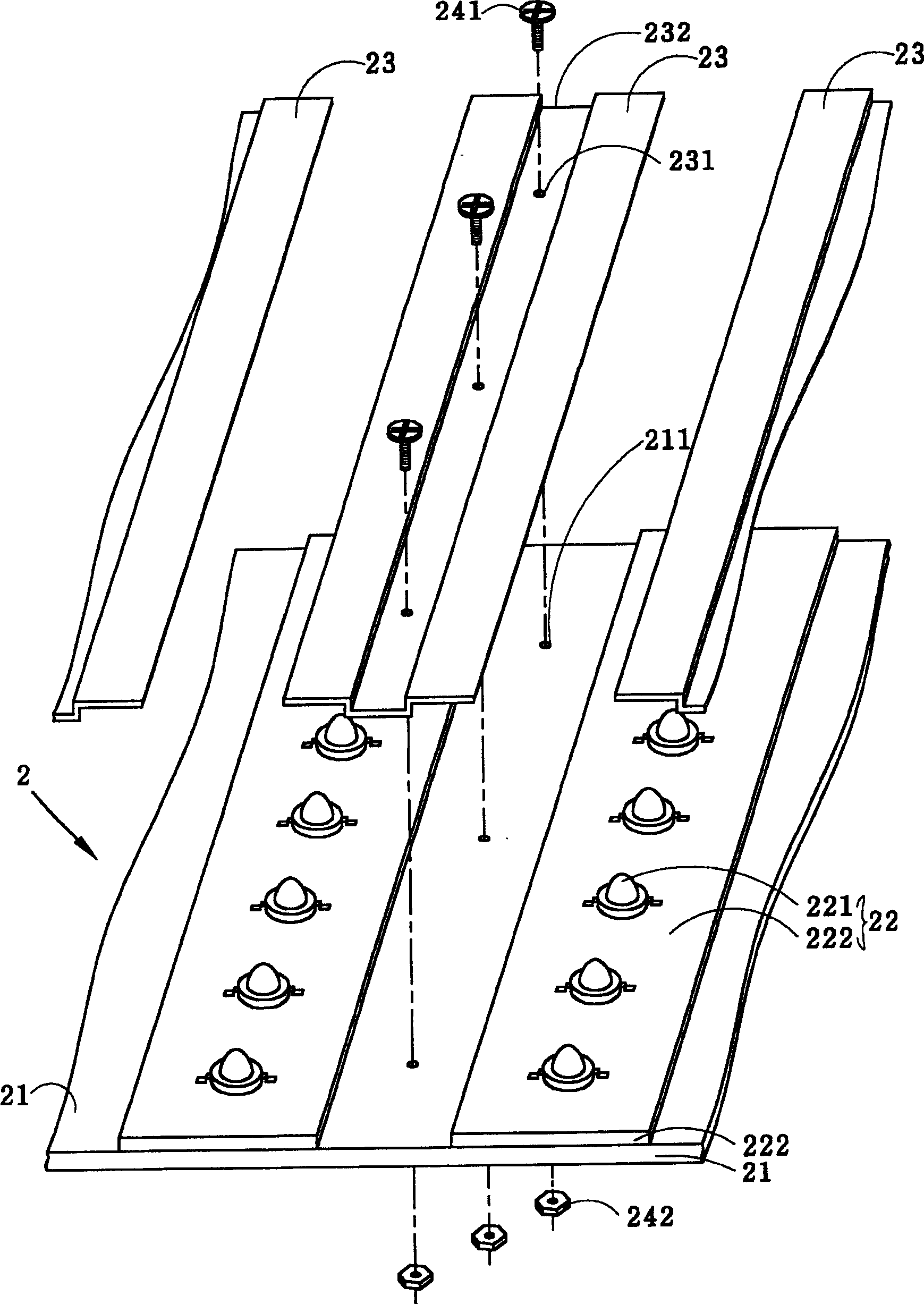
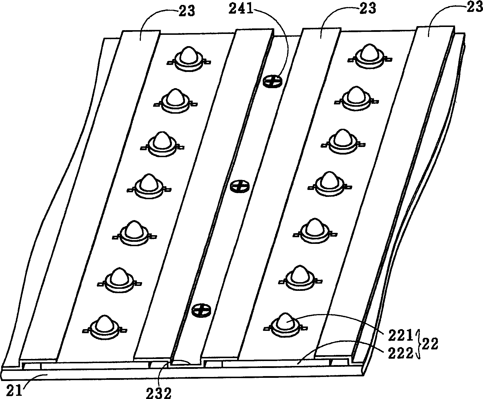
[0022] The following is a detailed description of the implementation of the backlight module of the present invention according to the accompanying drawings. The description of the backlight module and the light-emitting unit itself in the following description does not include the description of the detailed structure, composition and operating principle. The prior art is only cited here with emphasis to help explain the present invention. Moreover, the drawings of the relevant light emitting units in the following texts are not drawn according to the actual scale, and their function is only to express the characteristics of the present invention. Secondly, when each element or structure in the drawings of the embodiments of the present invention is described, it should not be regarded as a limited cognition, that is, when the following description does not particularly emphasize the limitation on the number, the spirit of the present invention and The scope of application ca...


PUM


Abstract

The back light module includes one back board, several light emitting units arranged on the back board in certain interval; and rigid base boards set between two adjacent light emitting units and with two edges pressing part of the adjacent light emitting units for fixing onto the back board. The rigid base boards fixed onto the back board with screws and nuts are superposed with the parallel arranged light emitting units so as to fix them onto the back board firmly. The light emitting unit fixing device of the present invention is simple and low in cost.

Description

(1) Technical field [0001] The invention relates to a fixing device, in particular to a fixing device for a light-emitting unit in a backlight module. (2) Background technology [0002] In the prior art, in a backlight module in a liquid crystal display, the method for fixing the light-emitting unit (unit) can be referred to figure 1 . The backlight module 1 is mainly composed of a backplane 11 and several light-emitting units 12 arranged in parallel on the backplane 11 at a distance. The aluminum substrate 122; wherein, the light-emitting element 121 is directly welded and assembled on the conductive circuit (not shown in the figure) on the aluminum substrate 122, and the heat energy generated during operation is conducted to the backplane 11 through the aluminum substrate 122 to escape . [0003] Continue to refer to figure 1 , the method used to fix the light-emitting unit 12 in the prior art is to first form several corresponding perforations (not shown in the figure...

Claims


Application Information

Patent Timeline
IPC IPC(8): F21S4/00G02F1/1333G02F1/1335
Inventor 刘邦炫
Owner AU OPTRONICS CORP
Why Eureka
Try Eureka