Robot pneumatic shillful hand

A robot and dexterous hand technology, which is applied in the field of robotic pneumatic dexterous hands, can solve the problems that the end manipulator of the robot cannot meet the production requirements, the clamping method is single, and it is difficult to control accurately, and achieve the effect of compact structure, flexible operation and easy processing

Inactive Publication Date: 2005-08-10
ZHEJIANG SCI-TECH UNIV
View PDF0 Cites 21 Cited by
  • Summary
  • Abstract
  • Description
  • Claims
  • Application Information

AI Technical Summary

Problems solved by technology

[0002] With the rapid development of modern science and technology and the continuous expansion of robot application fields, the original robot end effector can no longer meet today's production needs.
In order to overcom...

Method used


Image

  • Robot pneumatic shillful hand
  • Robot pneumatic shillful hand
  • Robot pneumatic shillful hand

Examples


Embodiment Construction

[0026] Below in conjunction with accompanying drawing and embodiment the present invention will be further described

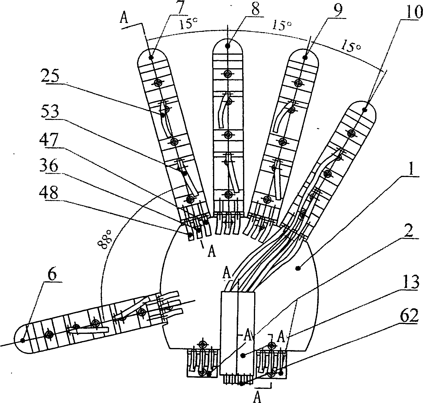
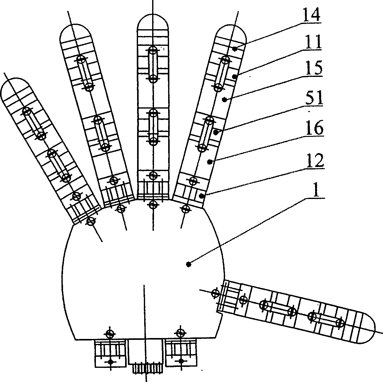
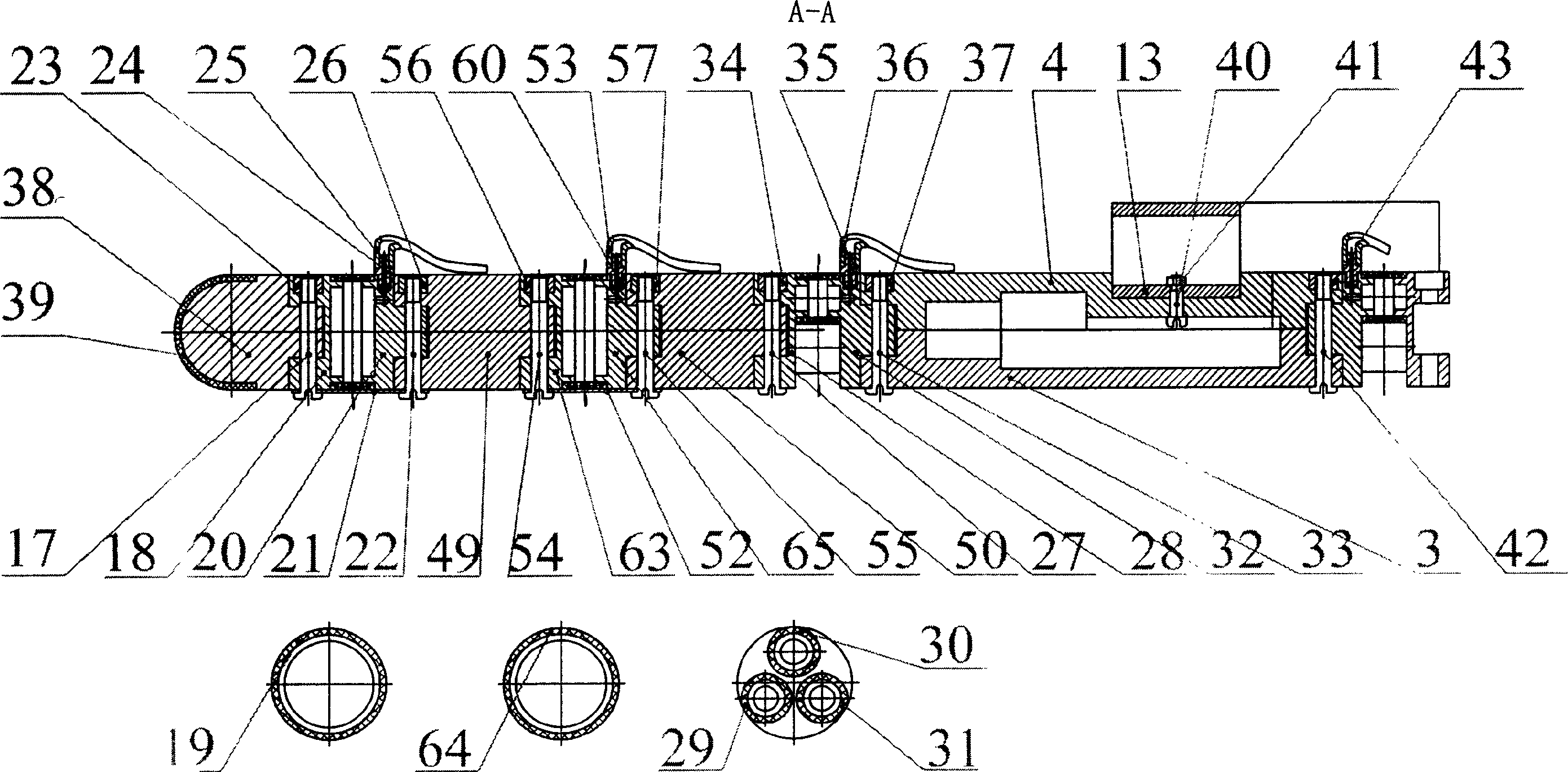
[0027] Such as figure 1 , 2 Shown, the present invention is made up of a palm 1, five fingers and wrist interface 2; Finger and wrist interface 2 are all connected on the mechanical interface 5 that palm 3 and back of hand 4 are combined; Five fingers are thumb 6, forefinger respectively 7. The middle finger 8, the ring finger 9 and the little finger 10, wherein the adjacent angles between the index finger 7, the middle finger 8, the ring finger 9 and the little finger 10 are all 15°, and the adjacent angle between the thumb 6 and the index finger 7 is 88°. Interfering motion of the fingers, each finger has three joints and four degrees of freedom. The wrist interface 2 is used to connect the palm 1 and the end of the robot manipulator to form a wrist joint with two degrees of freedom. Two pneumatic bending joints 11, 51 and a pneumatic ball joint 12 are dri...


PUM


Abstract

A pneumatic dexterous hand of robot is composed of a palm, 5 fingers with 3 joints and 4 freedoms for each finger, a wrist interface with 2 freedoms, and a leading trunk on the palm back and used for 25 pneumatic tubes of 5 fingers.

Description

technical field [0001] The invention relates to a robotic dexterous hand, in particular to a robotic pneumatic dexterous hand with five fingers, sixteen joints and 22 degrees of freedom. Background technique [0002] With the rapid development of modern science and technology and the continuous expansion of robot application fields, the original robot end effector can no longer meet today's production needs. In order to overcome the shortcomings of ordinary end effectors such as single clamping method, small moving space, lack of flexibility, and difficulty in precise control, a dexterous manipulator (referred to as dexterous hand) came into being. The dexterous hand has multiple degrees of freedom, can grasp objects of various shapes and materials, and can also perform fine manipulations on the grasped objects. Using it instead of a special gripper and installing it at the end of the robot manipulator can not only expand the working range of the robot, but also improve the...

Claims


Application Information

Patent Timeline
IPC IPC(8): B25J15/00B25J15/10B25J17/00
CPCB25J15/0009
Inventor 杨文珍竺志超赵匀
Owner ZHEJIANG SCI-TECH UNIV
Why Eureka
Try Eureka