
Motor rotor

A motor and rotor technology, applied in electric components, synchronous motors for single-phase current, manufacturing stator/rotor bodies, etc., can solve problems such as deterioration of motor characteristics, increase in cost, and deterioration of magnetic field intensity distribution

Inactive Publication Date: 2005-08-10
KK TOSHIBA +2
View PDF0 Cites 9 Cited by
  • Summary
  • Abstract
  • Description
  • Claims
  • Application Information

AI Technical Summary

Problems solved by technology

Ultimately, the inertial torque increases due to an increase in overall weight, etc., deteriorating the characteristics of the motor
cost also increased
[0007] In addition, in the above-mentioned existing structure, if the thickness of the frame 1 is not increased, and the ring 3 is not added, the magnetic flux φ flowing through the permanent magnet 2 cannot return fully, so the magnetic field intensity acting on the stator decreases, and the magnetic field The intensity distribution also deteriorates, the sound and vibration of the motor become larger, etc., and the characteristics deteriorate

Method used


Image

  • Motor rotor
  • Motor rotor
  • Motor rotor

Examples


Embodiment Construction

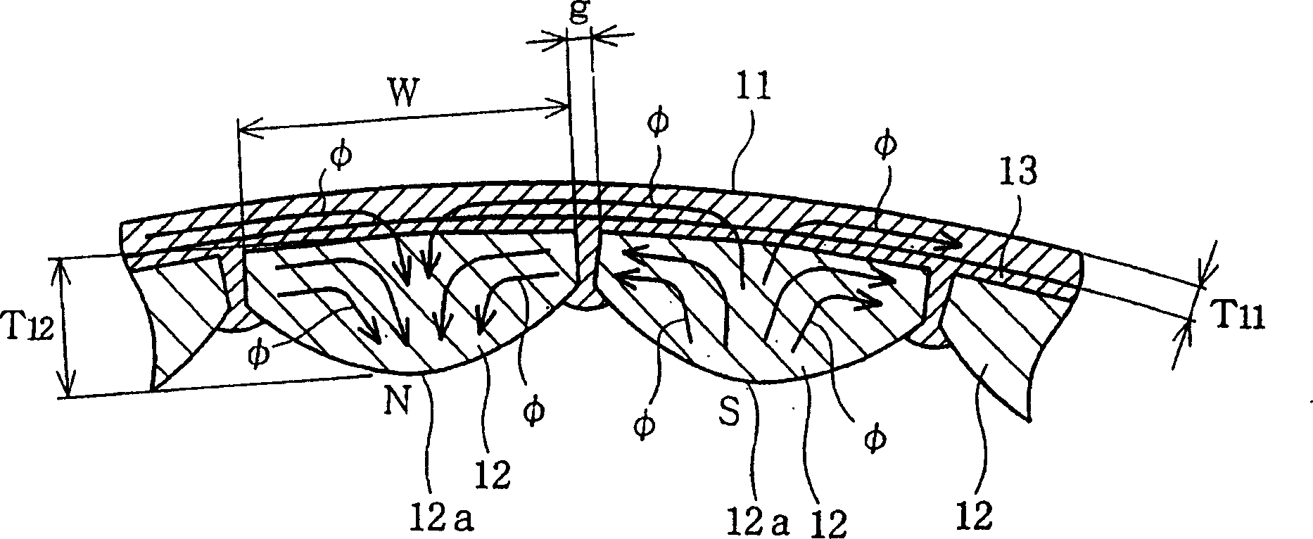
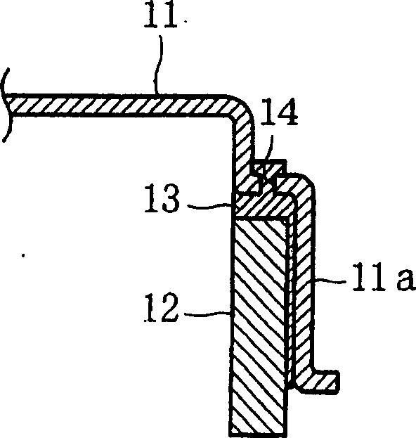
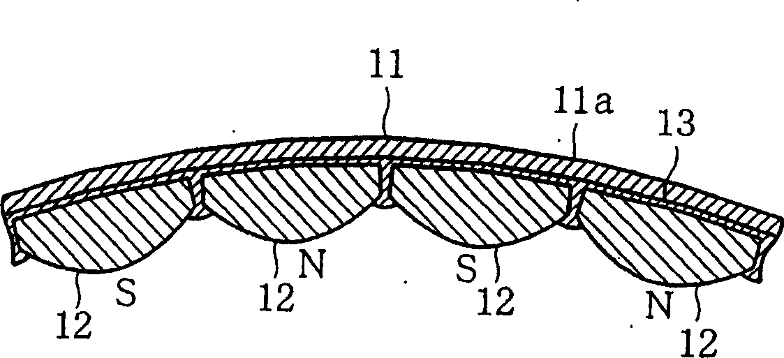
[0023] Below, refer to Figure 1 to Figure 3 A first embodiment of the present invention will be described.

[0024] First, in figure 2 and image 3 The frame 11 is shown in the middle, and the frame 11 is formed into a flat cylindrical container shape with a cover by stamping a magnetic material such as a steel plate, and the peripheral side portion 11a is located outside the periphery of the stator (not shown). Thus, in this case the motor is of the outer rotor type with the rotor located outside the periphery of the stator.

[0025] On the stator side of the frame 11, that is, the inner circular surface of the peripheral side portion 11a ( figure 2 Middle is left, image 3 The middle is the bottom), and a plurality of permanent magnets 12 are arranged on the entire circumference, so that the polarities of N and S are opposite alternately. In addition, the permanent magnets 12 are fixed to the frame 11 (circumferential side portion 11 a ) by using a molding 13 of synt...


PUM


Abstract

A motor rotor has a magnet (12) made from sintered magnetic powder in which magnetic flux flow is orientated pole-anisotropically. A plurality of the magnets (12) are arranged with alternating polarities on the stator of the frame (11) made from a magnetic body.

Description

technical field [0001] The present invention relates to a motor rotor formed by arranging permanent magnets on the stator side of a frame. Background technique [0002] In the past, provided Figure 5 and Figure 6 The structure shown acts as the rotor of the motor. In this structure, the frame 1 is made into a flat cylindrical container shape with a cover by using a magnetic material such as a steel plate, and its peripheral side portion 1a is located outside the periphery of a stator (not shown). So in this case the motor is of the outer rotor type with the rotor outside the stator perimeter. [0003] On the stator side of the frame 1, the inner circular surface of the peripheral side portion 1a ( Figure 5 middle left, Figure 6 lower middle), with multiple permanent magnets arranged along the entire circumference. The permanent magnet 2 is usually oriented such that Figure 6 The magnetic flux φ shown flows only from one side of the stator to the opposite side of th...

Claims


Application Information

Patent Timeline
Patent Type & Authority Applications(China)
IPC IPC(8): H02K1/22H02K1/27H02K15/03
CPCH02K1/2786H02K1/278H02K1/2791H02K1/27H02K1/22
Inventor 志贺刚
Owner KK TOSHIBA
Learn More