Spindle structure of a machine tool

A spindle and machine tool technology, applied in the field of spindle structure, can solve the problems of insufficient tool performance, high production cost, low transmission torque, etc., and achieve stable tool clamping state, reduce machining accuracy, and maintain tool clamping state. Effect

Inactive Publication Date: 2005-08-17
FANUC LTD
View PDF3 Cites 2 Cited by
  • Summary
  • Abstract
  • Description
  • Claims
  • Application Information

AI Technical Summary

Problems solved by technology

[0012] However, the above-mentioned structures have the following disadvantages: due to the small transmission torque between the spindle and the tool holder, the performance of the tool cannot be fully utilized, and the structure is complicated and the production cost is high.

Method used


Image

  • Spindle structure of a machine tool
  • Spindle structure of a machine tool
  • Spindle structure of a machine tool

Examples


Embodiment Construction

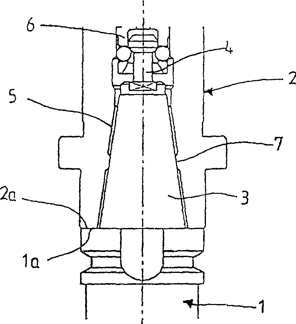
[0027] A first embodiment of a spindle structure of a machine tool according to the present invention will be described with reference to FIG. 1 .

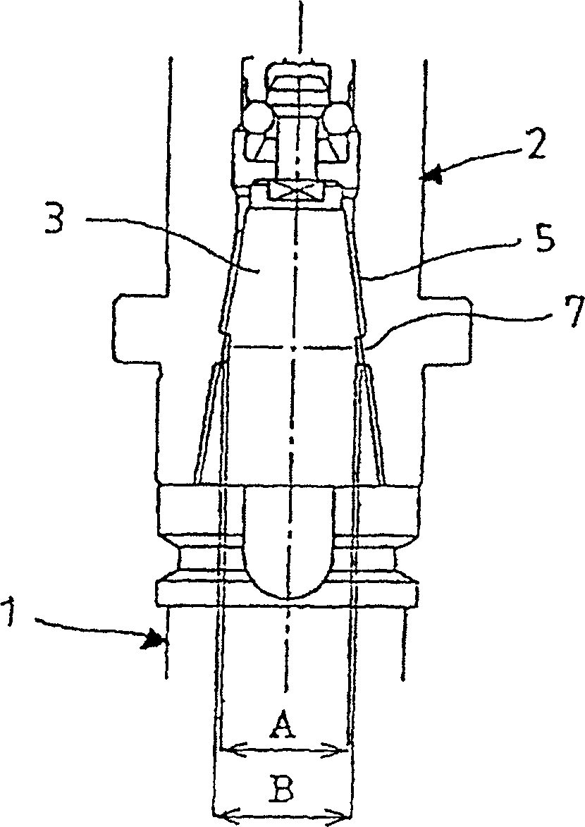
[0028] In the spindle structure shown in Fig. 1, the tool holder 1 with cutting tools and other tools (not shown) installed is installed on the spindle 2 of the machine tool, and the tool is connected to the spindle 2, so that the movement of the spindle 2 can be transmitted to on the knife.

[0029] In the central portion of the end surface 1 a of the tool holder 1 , a convex conical portion 3 is integrally provided, and the central axis thereof coincides with the central axis of the tool holder 1 . On the top of the convex conical portion 3 , a pull bolt 4 is erected along the central axis of the convex conical portion 3 .

[0030] At the central portion of the end surface 2 a of the main shaft 2 , a concave conical portion 5 is formed, the central axis of which coincides with the central axis of the main shaft 2 . At the bott...


PUM


Abstract

A tool holder is attached to a spindle by the contacting of the projecting cone part and end surface of the tool holder with the recessed cone part and end surface of the spindle respectively. A toroidal cone section is provided on the inner side surface of the recessed cone part of the spindle so as to protrude inward. The diameter of the toroidal cone section is formed smaller than the diameter of the section of the projecting cone part of the tool holder that abuts the toroidal cone section.

Description

technical field [0001] The present invention relates to a main shaft structure of a machine tool capable of holding and removing a tool holder from the main shaft. Background technique [0002] To connect the tool holder on which tools such as cutting tools are mounted to the spindle of the machine tool, first, the convex conical portion provided on the end surface of the tool holder is fitted into the concave conical portion formed on the top end of the spindle. Then, the draw bolts arranged on the top of the convex conical portion of the tool holder are pulled upwards by the draw bar arranged on one side of the main shaft, so that the convex conical portion (conical surface) of the tool holder is aligned with the concave conical portion of the main shaft. (conical surface) contact. [0003] However, in this way, the combination of the tool holder and the spindle through the contact between the conical surfaces has the following disadvantages. When an external force is ap...

Claims


Application Information

Patent Timeline
Patent Type & Authority Applications(China)
IPC IPC(8): B23B31/117B23B19/02B23B31/00B23B31/26
CPCB23B2231/0204B23B31/006B23B2231/0288Y10T408/95B23B31/261Y10T409/309464Y10T409/309408
Inventor 渡边训夫藤元明彦室田真弘
Owner FANUC LTD
Why Eureka
Try Eureka