
Steel tent top cloth installation adjusting structure

A technology of installation adjustment and top cloth, which is applied in the direction of tents/canopies, building types, buildings, etc. It can solve the problems of inability to realize expansion and contraction, inability to install, and inconvenient insertion into the bag body, so as to achieve convenient and labor-saving operation and perfect overall functions , strong practical effect

Pending Publication Date: 2019-09-24
盛基家居用品开发(嘉善)有限公司
View PDF0 Cites 0 Cited by
  • Summary
  • Abstract
  • Description
  • Claims
  • Application Information

AI Technical Summary

Problems solved by technology

[0002] When the existing steel tent is installed, the steel pipe top beam without telescopic function is inserted into the bag body pre-set on the edge of the tent top cloth. Since the traditional plastic plug only blocks the inner opening of the steel pipe top beam, it can The sealing function reduces the welding of the seal and the plastic parts are not easy to wear the top cloth after the top cloth is installed, but because the whole steel pipe top beam cannot be stretched, it is inconvenient to insert into the bag body, and the size control must be very accurate when installing the top cloth of the tent , if the size of the top cloth is slightly deviated, there will be defects that the top cloth of the tent is torn or cannot be installed, and the overall effect is not good

Method used


Image

  • Steel tent top cloth installation adjusting structure
  • Steel tent top cloth installation adjusting structure
  • Steel tent top cloth installation adjusting structure

Examples


Embodiment Construction

[0015] In order to enable those skilled in the art to better understand the technical solution of this experimental novelty, the preferred embodiments of the present invention are described below in conjunction with specific examples, but it should be understood that these descriptions are only to further illustrate the characteristics and advantages of the present invention, and It is not a limitation on the patent claims of the invention. Based on the embodiments of the present invention, all other embodiments obtained by persons of ordinary skill in the art without making creative efforts belong to the protection scope of the present invention.

[0016] The present invention will be further described below in conjunction with the accompanying drawings and preferred embodiments.

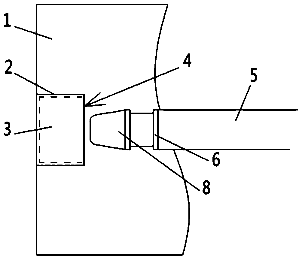
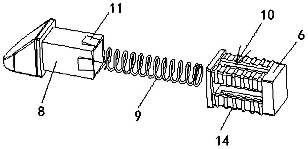
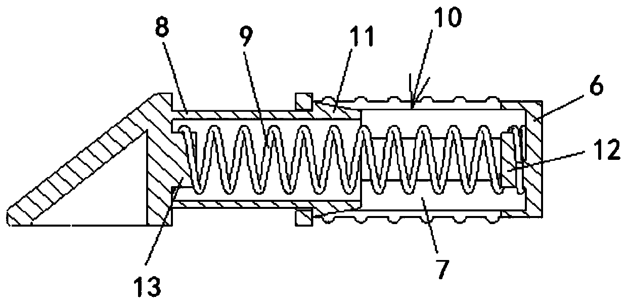
[0017] see Figures 1 to 3 As shown, a steel tent top cloth installation and adjustment structure involved in this embodiment includes a top cloth main body 1, a splicing cloth 2 is arranged on th...


PUM


Abstract

The invention discloses a steel tent top cloth installation adjusting structure. The steel tent top cloth installation adjusting structure comprises a top cloth main body, a spliced cloth is arranged on the top cloth main body, part edges of the spliced cloth and the top cloth main body are sewed to from a bag body, and the bag body is provided with a bag opening. The steel tent top cloth installation adjusting structure further comprises a tube body penetrating through the bag opening and a part of the tube body extending into the tube body, and a telescopic drain plug is arranged on the end part of the tube body; the telescopic drain plug comprises a drain plug tail seat arranged on the end part of the tube body, a telescopic groove with a groove opening facing the bag opening is formed in the drain plug tail seat, a telescopic head is slidably connected into the telescopic groove, a spring is further arranged in the telescopic groove, wherein one end of the spring abuts against the groove bottom of the telescopic groove, and the other end of the spring abuts against the telescopic head, a limiting groove extending in the length direction of the limiting groove is formed in the side wall of the drain plug tail seat, the limiting groove communicates with the telescopic groove, and a limiting block slidably connected to the limiting groove is arranged on the side wall of the telescopic head. The steel tent top cloth installation adjusting structure has the characteristics of being capable of being extended and contacted and convenient installation.

Description

technical field [0001] The invention relates to a tent roof fabric installation structure, more specifically, it relates to a steel tent roof fabric installation and adjustment structure. Background technique [0002] When the existing steel tent is installed, the steel pipe top beam without telescopic function is inserted into the bag body pre-set on the edge of the tent top cloth. Since the traditional plastic plug only blocks the inner opening of the steel pipe top beam, The sealing effect reduces the welding of the seal and the plastic parts are not easy to wear the top cloth after the top cloth is installed. However, since the whole steel pipe top beam cannot be stretched, it is inconvenient to insert into the bag body, and the size control must be very accurate when installing the top cloth of the tent. , if the size of the top cloth is slightly deviated, there will be defects that the top cloth of the tent is torn or cannot be installed, and the overall effect is not ...

Claims


Application Information

Patent Timeline
Patent Type & Authority Applications(China)
IPC IPC(8): E04H15/64
CPCE04H15/64E04H15/642E04H15/646
Inventor 朱燕青
Owner 盛基家居用品开发(嘉善)有限公司
Learn More