Helical spring and suspension gear

A coil spring and helical technology, used in elastic suspensions, suspensions, springs/shock absorbers, etc., can solve the problems of large buckling displacement, cannot be manufactured at low cost, and cannot be applied to occasions with limited installation space.

Active Publication Date: 2005-08-17
NHK SPRING CO LTD
View PDF2 Cites 12 Cited by
  • Summary
  • Abstract
  • Description
  • Claims
  • Application Information

AI Technical Summary

Problems solved by technology

However, since it is not clear how the curved coil springs are held in a straightened state, in addition, curved coil springs suitable for wheel suspensions cannot be manufactured at low cost
Moreover, since

Method used


Image

  • Helical spring and suspension gear
  • Helical spring and suspension gear
  • Helical spring and suspension gear

Examples


Embodiment Construction

[0038] Embodiments applicable to the present invention will be described in detail below with reference to the accompanying drawings.

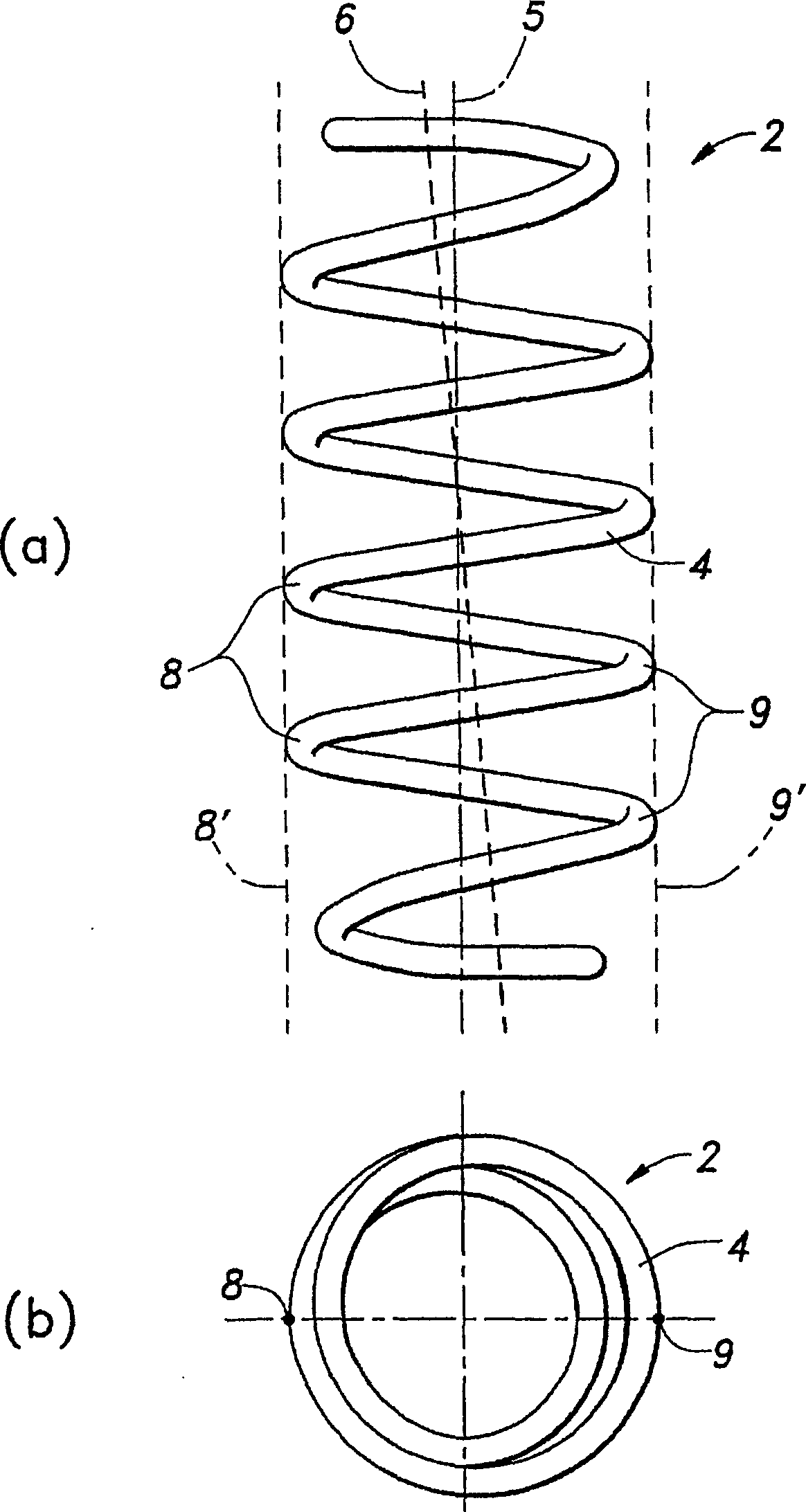
[0039] figure 2 a and figure 2 b represents a compression coil spring 2 with a mounting ring portion in the form of the prior art. In general, a compression coil spring is formed by winding a helical wire 4 around a central axis 5 . Due to the limited number of turns, it cannot be completely symmetrical around the central axis 5 , so the load axis 6 is slightly inclined relative to the central axis 5 . The load axis 6 can be regarded as the direction of the reaction force generated on the spring 2 when a load is applied in the direction of the central axis 5 .

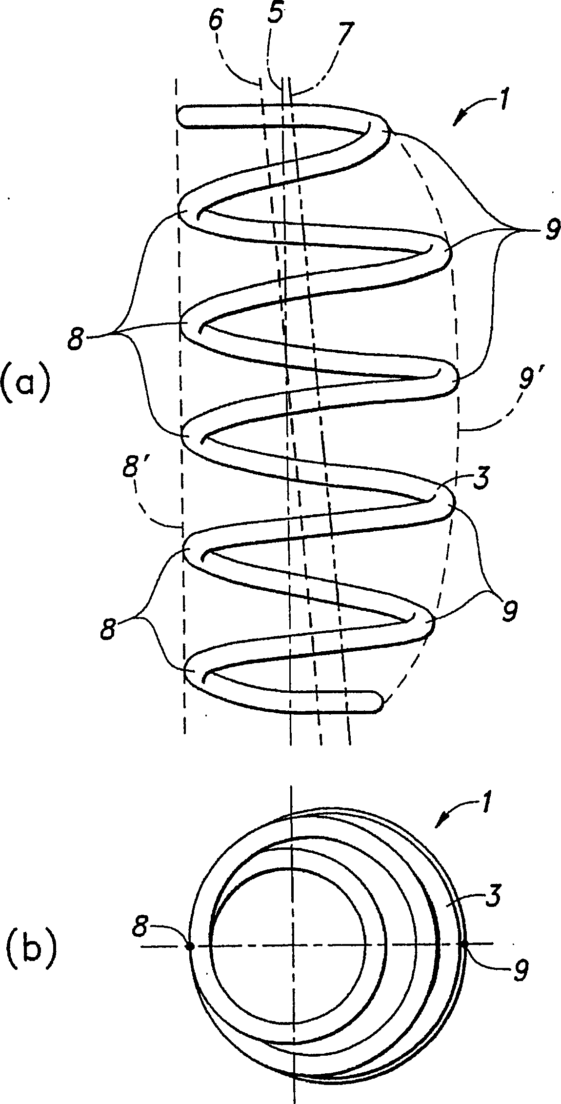
[0040] figure 1 a and figure 1 b represents the D-shaped compression coil spring 1 based on the present invention. One side position 8 is used as the reference position for changing the winding diameter, and the straight line 8' connecting one side position 8 is roughly parallel...


PUM


Abstract

To provide a coil spring with a load axis offset from a geometric axis, and to provide a vehicular suspension system using the same. The coil spring 1 is wound with its winding diameter larger at an intermediate in the axial direction than at the end. At one sidewise position 8, the contour of a coil is aligned almost straight to the axial direction, while at the other sidewise position 9, the contour of the coil is swollen to be protruded outward. Namely, the contour of the coil is in a D-shape in view from a specified sidewise direction. Thus, the coil spring is actualized with the load axis offset in parallel to the axis without being affected by buckling deformation.

Description

technical field [0001] The present invention relates to a coil spring having a load shaft offset with respect to a geometric central axis and a suspension device for a vehicle using the coil spring. Background technique [0002] In the prior art such as a strut type suspension device for automobiles etc., there is a suspension device in which an assembly consisting of a cylindrical shock absorber and a compression coil spring is assembled in such a manner that a vehicle body and a wheel bracket are connected, wherein , The barrel-type shock absorber has an oil cylinder filled with oil and a piston accommodated in the oil cylinder, and a compression coil spring is arranged around the barrel-type shock absorber. However, the force input from the tire does not necessarily coincide with the axis of the shock absorber, and since it is accompanied by a lateral load, there is a problem that the lateral load and moment act on the sliding part between the cylinder and the piston of t...

Claims


Application Information

Patent Timeline
IPC IPC(8): B60G15/06B60G11/16F16F1/04F16F1/06
CPCA47C1/032A47C3/20A47C7/02A47C7/402A47C7/441
Inventor 浜野俊雄加藤友丈尾山二郎上田政尚仲村崇广
Owner NHK SPRING CO LTD
Why Eureka
Try Eureka