Vehicle lamp unit

A technology for lamps and vehicles, which is applied in the direction of headlights, vehicle parts, vehicle lighting systems, etc., can solve the problem of inability to spread light with large horizontal and long light distribution patterns, and achieve the effect of improving the utilization rate of light beams

Inactive Publication Date: 2005-08-17
KOITO MFG CO LTD
View PDF1 Cites 17 Cited by
  • Summary
  • Abstract
  • Description
  • Claims
  • Application Information

AI Technical Summary

Problems solved by technology

[0007] If the vehicle lamp unit described in the above-mentioned "Patent Document 1" is used, the beam utilization efficiency of the light from the light-emitting diode can be improved, but there is a problem that the light irradiation from the lamp unit cannot form a horizontal direction with a large diffusion angle. Problems with light distribution graphics

Method used


Image

  • Vehicle lamp unit
  • Vehicle lamp unit
  • Vehicle lamp unit

Examples


Embodiment Construction

[0086] Hereinafter, embodiments of the present invention will be described with reference to the drawings.

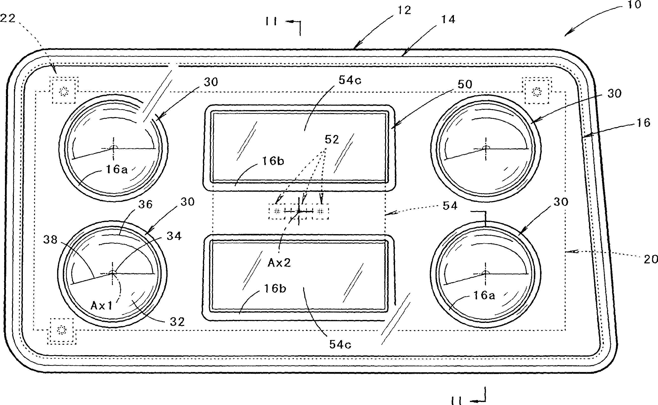
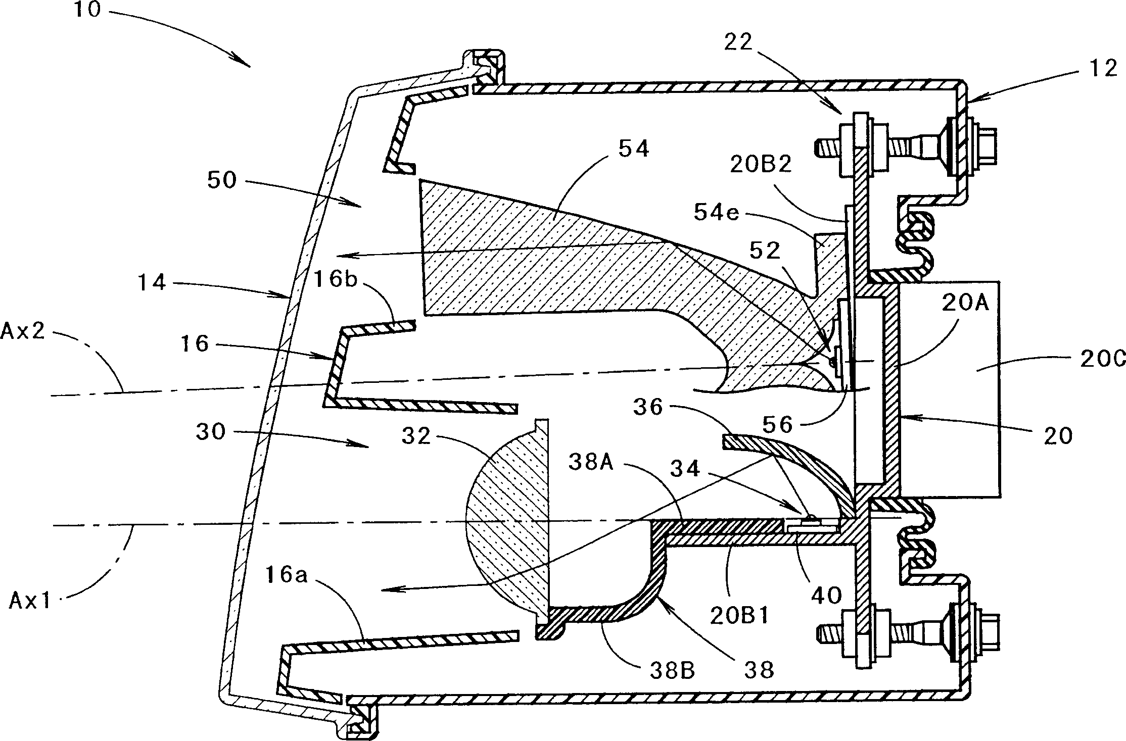
[0087] figure 1 is a front view showing a vehicle lighting fixture according to an embodiment of the present invention, figure 2 Yes figure 1 The II-II line profile.

[0088] As shown in these figures, the vehicle lighting fixture 10 of this embodiment is a headlight provided on the right side of the front end of the vehicle. Five lamp units 30, 50 are accommodated in the lamp chamber.

[0089] The four lamp units 30 out of the five lamp units 30 and 50 have a circular outer shape in front view and are arranged in two upper and lower stages. In addition, the outer shape of the remaining one lamp unit 50 in front view is set to be a rectangle, and is arranged in the center thereof so that two of the four lamp units 30 are arranged on the left and right sides.

[0090] In the above-mentioned lamp chamber, an inner panel 16 is arranged along the light-transmitting co...


PUM


Abstract

A pair of upper and lower incidence surfaces are formed on a rear face of a translucent member disposed to cover three light-emitting elements. On upper and lower sides of the incidence surfaces are formed a pair of reflection surfaces for causing light emitted by the light-emitting elements and having entered the translucent member to internally reflect forward. Each of the incidence surfaces is formed from a cylindrical convex-curved surface extending horizontally. Each of the reflection surfaces is formed from a parabolic cylindrical curved surface whose focal line passes through a virtual image point of each of the light-emitting elements formed by the corresponding incidence surfaces. By the above configuration, light emitted by the light-emitting elements is caused to internally reflect in such a manner as to diffuse in the horizontal direction, and not to diffuse in the vertical direction, thereby exiting forward from a pair of exit surfaces.

Description

technical field [0001] The present invention relates to a vehicle lamp unit using a light emitting element such as a light emitting diode as a light source. Background technique [0002] In recent years, vehicle lamp units using light emitting diodes as light sources have been widely used. [0003] At this time, "Patent Document 1" describes a vehicle lamp unit including a light emitting diode arranged to face the front of the lamp unit, and a translucent member arranged to cover the light emitting diode from the front side. [0004] This lamp unit for a vehicle has a structure in which the light from the light emitting diode incident on the rear end of the light-transmitting member is guided to the front end surface of the light-transmitting member, and is emitted from the front end surface through a projector arranged in front of the light emitting diode. The lens shines toward the front of the lamp unit. [0005] Patent Document 1: JP-A-2002-50214 [0006] In vehicle l...

Claims


Application Information

Patent Timeline
Patent Type & Authority Applications(China)
IPC IPC(8): F21S8/12F21S8/10F21V7/00F21V13/00F21Y101/02
CPCF21V5/04F21S48/236F21S48/1163F21S48/25F21S48/1329F21S48/1159F21V7/0091F21Y2101/02F21S48/1241F21Y2115/10F21S41/143F21S41/155F21S41/24F21S41/322F21S43/315F21S43/50F21S41/153F21S41/148
Inventor 小松元弘
Owner KOITO MFG CO LTD
Why Eureka
Try Eureka