Power moment strengthening technique for fixing device for rotary cleaning element removing dirt inside pipe

A technology for fixing devices and cleaning parts, which is applied in the direction of cleaning rotating equipment, cleaning heat transfer devices, cleaning hollow objects, etc., and can solve the problems of affecting the rotation torque, large friction resistance torque, and insufficient reliability.

Inactive Publication Date: 2005-08-24
HUNAN UNIV OF TECH
View PDF2 Cites 7 Cited by
  • Summary
  • Abstract
  • Description
  • Claims
  • Application Information

AI Technical Summary

Problems solved by technology

[0003] The technical problem to be solved by the present invention is that the existing nozzle fixing device of the rotary cleaning part in the heat transfer tube has a large frictional resistance moment, the inlet swirl affects the rotation moment, and the reliability is not high enough. The power torque enhancement technology of the device has the advantages of small resistance torque, high reliability, and can also generate a large pre-rotation recoil torque, etc., so that the automatic rotary cleaning and anti-scaling components can be more widely used in lower flow rates, Or heat transfer equipment with high dirt cleaning resistance

Method used


Image

  • Power moment strengthening technique for fixing device for rotary cleaning element removing dirt inside pipe

Examples


Embodiment Construction

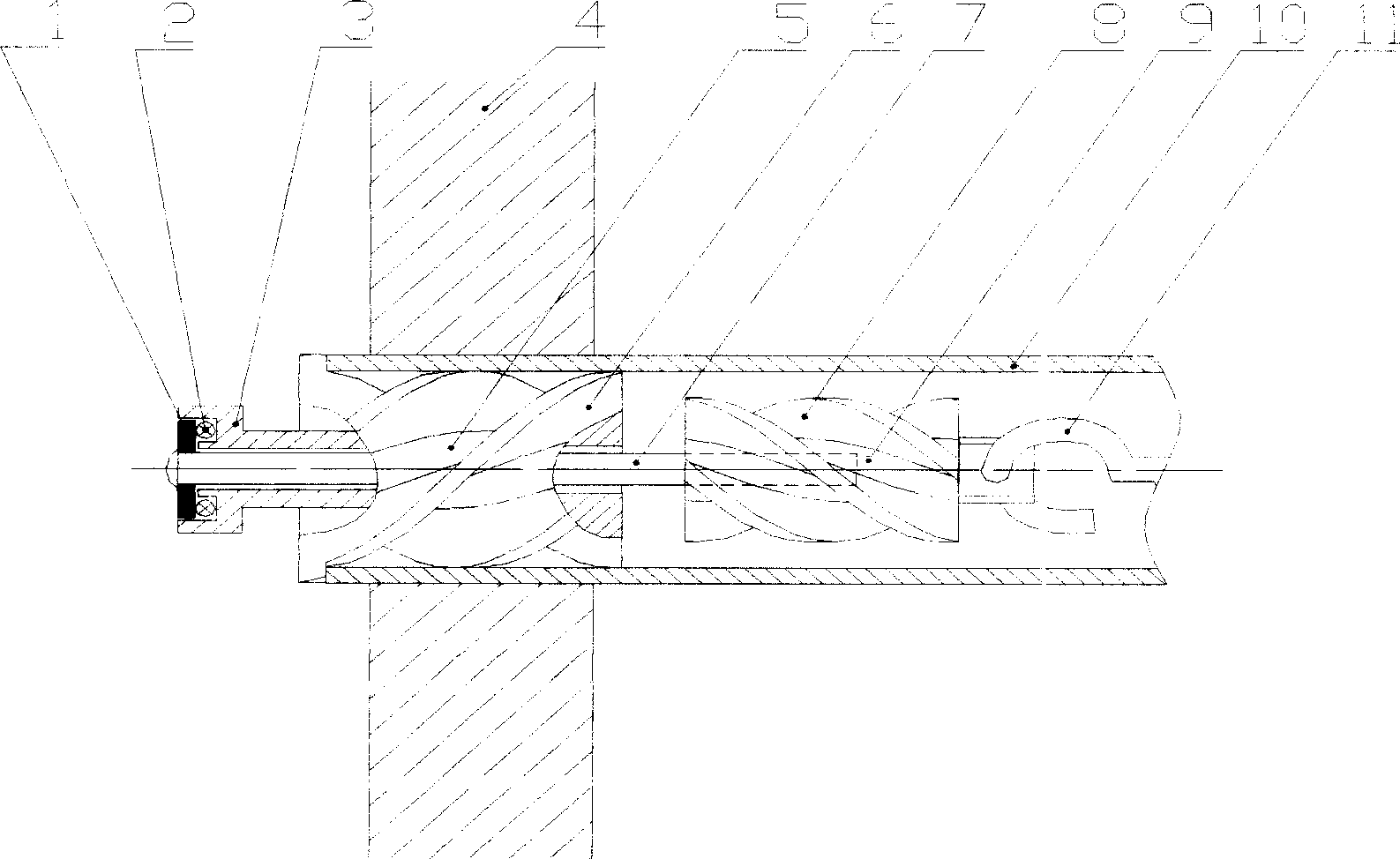
[0011] The specific embodiment of patent of the present invention is illustrated below in conjunction with accompanying drawing:

[0012] See figure 1 . The bearing bowl 3 and the reverse spiral flow channel 5 are of an integral structure, or may be of a split structure. The rotating shaft 7 is riveted or welded to the bearing cap 1 and fixed. The helical direction of the reverse helical channel 5 is opposite to the helical (or helical) direction of the rotating cleaning element 11 . The plastic power wheel 9 is integrally formed with the rotating shaft 7 during injection molding. The rotating shaft 7 is connected with a rotating cleaning element 11 . The diameters of the spiral guide fins 6 and the power wheel fins 8 are smaller than the inner diameter of the heat transfer tube 10 . During production, the bearing cover 1, the rolling ball 2, the bearing bowl 3, the reverse spiral flow channel 5, the rotating shaft 7 and the power wheel 9 can be assembled into an integral...


PUM


Abstract

A technique for increasing the kinetic moment of the fixed for the rotary washing part used to remove the dirt inside pipe features that the fluid coming in pipe flows through the reverse spiral channed at the entrance of heat transfer pipe to become a large-radius high-speed cyclone stream to directly flush the kinetic wheel, so generating a large kinetic moment.

Description

technical field [0001] The invention relates to a dynamic torque strengthening technology of a fixing device for a rotating dirt cleaning part in a pipe. It can be applied to on-line rotary cleaning and anti-scaling and heat transfer enhancement of various shell and tube heat transfer equipment (such as heat exchangers, condensers, evaporators, etc.). Background technique [0002] French patent (FR25545209 and Chinese patent (CN2465140Y, CN2413319Y) and other disclosed technologies for cleaning the dirt in the heat transfer tube and the rotary twisted belt cleaning technology, the axial fixation of the rotary twisted belt is sliding friction, and its frictional resistance torque is relatively large, and the spiral twisted belt The smaller the pitch, the greater the axial force that the helical twisted belt bears, and the greater the corresponding frictional resistance moment, which is exactly the opposite of the heat transfer effect of the helical twisted belt, which is the ...

Claims


Application Information

Patent Timeline
Patent Type & Authority Applications(China)
IPC IPC(8): B08B9/04F28G3/00
Inventor 彭德其俞天兰俞秀民吴金香蒋少青林伟璐支校衡刘桂英
Owner HUNAN UNIV OF TECH
Why Eureka
Try Eureka