Apparatus for absorbing vibration of compressor

A technology for compressors and compressor housings, which is applied to components of pumping devices for elastic fluids, machines/engines, non-rotational vibration suppression, etc., and can solve problems such as component performance degradation, noise generation, and shortened component life.

Inactive Publication Date: 2005-08-24
LG ELECTRONICS INC
View PDF0 Cites 18 Cited by
  • Summary
  • Abstract
  • Description
  • Claims
  • Application Information

AI Technical Summary

Problems solved by technology

However, since the suction pipe 103 and the discharge pipe 105 connected to the compressor housing 101 are respectively connected to other parts such as a heat exchanger, the vibration generated by the compressor is transmitted to the above parts along the suction pipe 103 and the discharge pipe 105, Thus causing performance degradation of components, shortening the life of these components, and vibrating to generate noise

Method used


Image

  • Apparatus for absorbing vibration of compressor
  • Apparatus for absorbing vibration of compressor
  • Apparatus for absorbing vibration of compressor

Examples


Embodiment Construction

[0023] Reference will now be made in detail to the preferred embodiments of the present invention, examples of which are illustrated in the accompanying drawings.

[0024] There may be several embodiments of the device for absorbing vibrations of a reciprocating compressor according to the invention, the most preferred embodiment being described below.

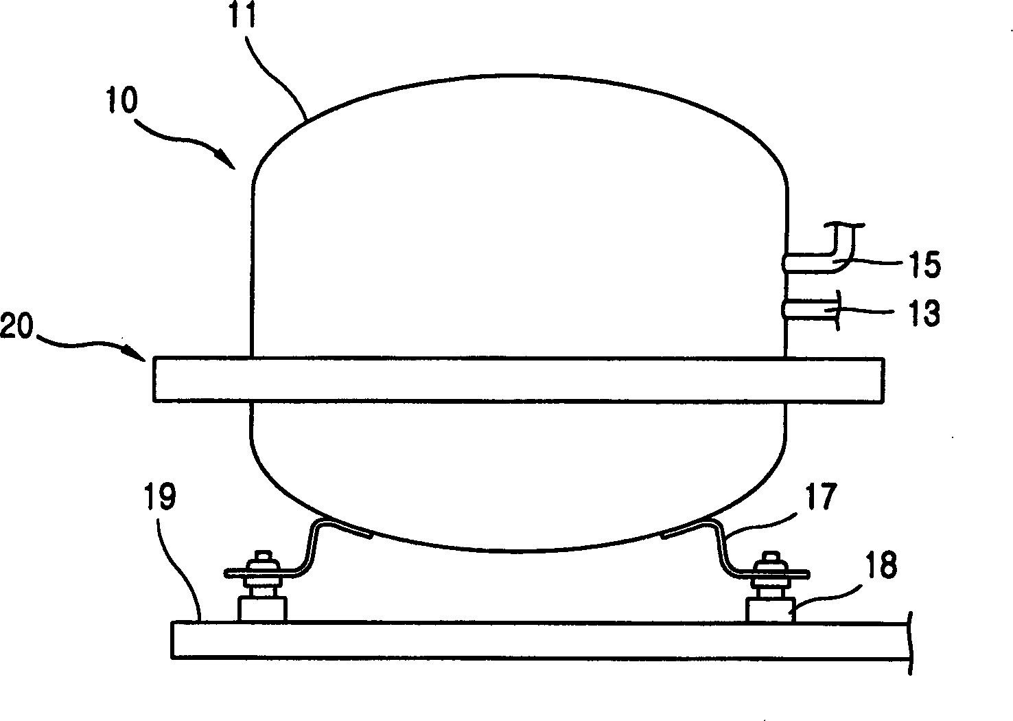
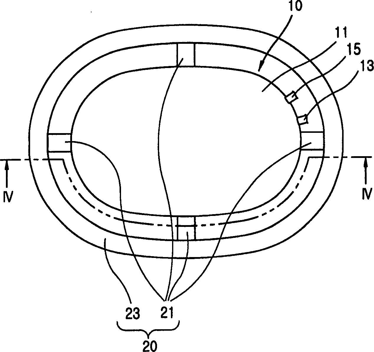
[0025] figure 2 shows a side view of a compressor provided with means for absorbing vibrations according to a first embodiment of the invention, image 3 shows a plan view of a compressor provided with means for absorbing vibrations according to a first embodiment of the invention, and Figure 4 yes image 3 Sectional view taken along line IV-IV.

[0026] The compressor according to the present invention includes: a compressor body 10 for compressing fluid;

[0027] The compressor main body 10 includes a housing 11 with a certain closed space; a motor part (not shown) installed in the housing 11 for generating driving for...


PUM


Abstract

An apparatus for absorbing vibration of a compressor includes: an elastic body mounted at an outer surface of a compressor case and elastically deformed when vibration is generated at a compressor; and a mass body connected to the elastic body, resonating with the compressor, for absorbing vibration of the compressor. Accordingly, vibration of the compressor is reduced so that noise and reliability degradation of a component due to the vibration can be reduced.

Description

technical field [0001] The present invention relates to a device for absorbing vibration of a compressor, and more particularly to such a device for absorbing vibration of a compressor, which can reduce noise due to vibration and improve compressor performance by reducing vibration of the compressor. reliability. Background technique [0002] In general, a compressor is a device that converts the mechanical energy of a compressible fluid into compression energy. [0003] figure 1 A side view showing a conventional compressor installation state. As shown in the figure, the compressor includes a casing 101 having an accommodation space therein; a compression section (not shown) accommodated inside the casing 101, fluid to be compressed; and a motor section ( not shown) for providing driving force to the compression part. [0004] A suction pipe 103 for sucking fluid and a discharge pipe 105 for discharging compressed fluid are respectively connected to the casing 101 of th...

Claims


Application Information

Patent Timeline
Patent Type & Authority Applications(China)
IPC IPC(8): F04B17/00F04B35/00F04B39/00F04B39/12F04C29/00F16F7/104F16F15/04
CPCF16F7/104F04B39/0027F04B39/121F04B39/0044F16F15/02F16F15/28F05B2260/964F05B2260/962F05B2210/14F05B2210/12Y10S417/902
Inventor 李东勋尹宁焄金容九李泰熹
Owner LG ELECTRONICS INC
Why Eureka
Try Eureka