Power system neutral point compound operation method

An operation method and power system technology, applied to electrical components, circuit devices, AC network circuits, etc., can solve the problem that the three-phase voltage balance cannot be solved at the same time to eliminate the single-phase ground fault, the arc suppression coil cannot be eliminated, and there are many power outage accidents on the line and other issues, to achieve the effect of improving the operation level of the power grid, reducing losses, and reducing power grid outage accidents

Inactive Publication Date: 2005-08-24
刘渝根
View PDF0 Cites 5 Cited by
  • Summary
  • Abstract
  • Description
  • Claims
  • Application Information

AI Technical Summary

Problems solved by technology

However, the improvement of the compensation degree of the arc suppressing coil hides that when the power grid is single-phase grounded due to a lightning strike, the short-circuit arc current at the ground point after the inductive current compensation of the arc suppressing coil changes from the single-phase grounding capacitive current to the inductive current , because the compensation of the arc suppression coil is too large, that is, the inductance current is too large, the current value of the grounding point after compensation will often exceed 10A, so that the single-phase grounding arc current is not easy to extinguish, that is to say, the arc suppression coil does not achieve elimination. The purpose of a single-phase-to-ground short-circuit fault will eventually lead to the tripping of the line
All in all, for the 35kV power grid in mountainous areas, the current operation mode of the neutral point of the power system cannot simultaneously solve the problem of three-phase voltage balance during normal operation and the problem of single-phase grounding short-circuit current arc extinguishing by arc suppression coils to eliminate single-phase grounding faults
Therefore, the 35kV power grid in mountainous areas often has frequent lightning trips and frequent power outages, resulting in huge economic losses.

Method used


Image

  • Power system neutral point compound operation method
  • Power system neutral point compound operation method
  • Power system neutral point compound operation method

Examples


Embodiment

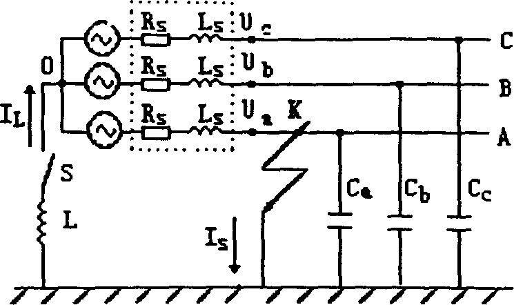
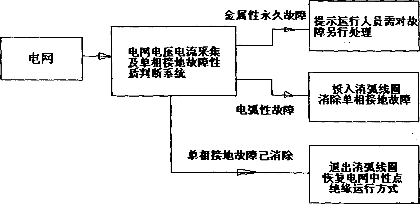
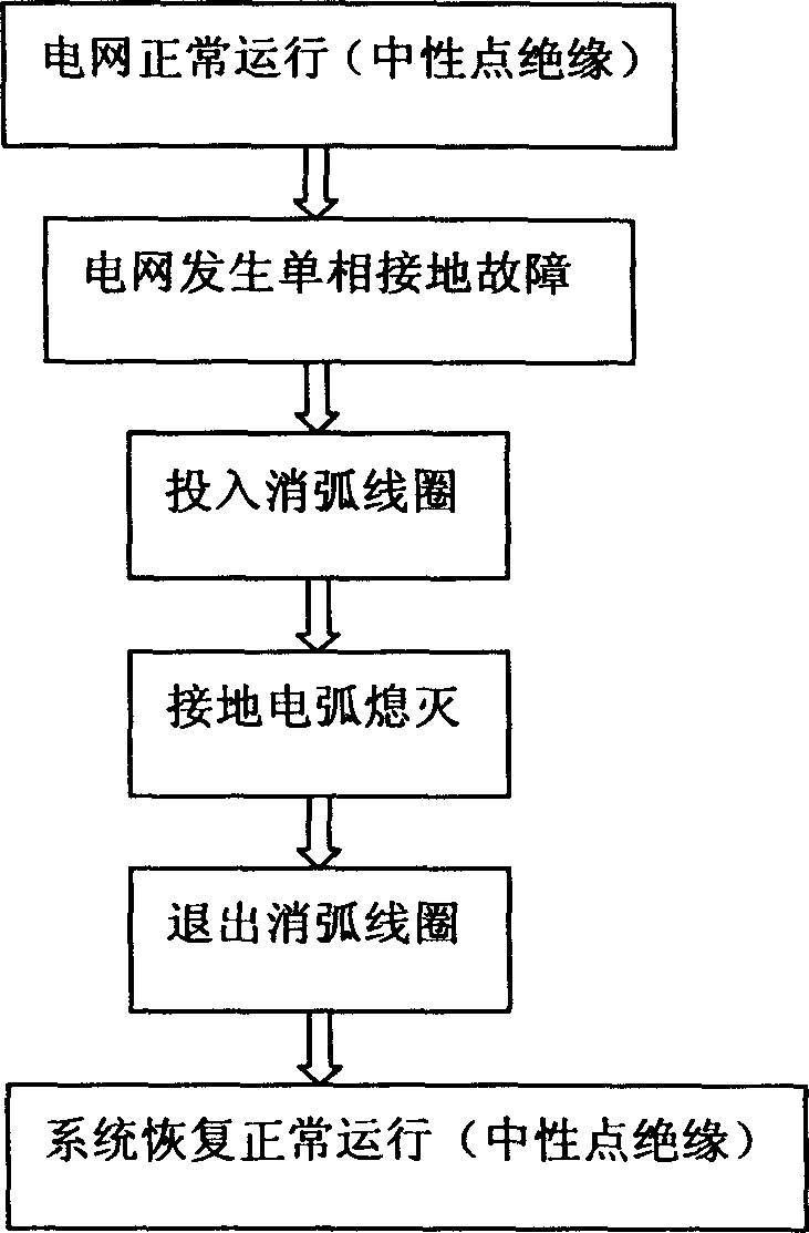
[0015] See figure 1 , figure 2 , image 3 Can know: the mode of operation of the present invention divides two kinds of situations:

[0016] a. When the power grid is in normal operation, the neutral point insulation operation mode is adopted;

[0017] b. When a single-phase ground fault occurs on the line, such as a single-phase ground fault caused by a lightning strike on the line, the grid voltage and current acquisition and single-phase ground fault nature judgment system in the arc suppression coil automatic switching device collects signals such as grid voltage and current , to judge the nature of the single-phase ground fault, if it is a permanent metal fault, it will automatically output information to prompt the ground fault to be processed separately. If it is an arc fault, use the automatic switching device to quickly switch on the arc suppression coil, use the inductance current of the arc suppression coil to reduce the capacitance current of the ground point a...


PUM


Abstract

This invention adopts neutral isolation function mode as the electric net in function: when the circuit is mono-directionally grounded, through the collection of the voltage and current signals of the electric net, judge the failure of the mono-directionally grounding as the metal permanent failure to output the information hinting to process the grounded failure, as to the electric arc failure, uses automatic delivering device to deliver arc-distinguishing coil to eliminate the mono-directional grounded failure, when the grounded failure is wiped off, exit the arc-distinguishing coil and resume the neutral isolation mode of the working order of the electric net. This invention can fully exert the mono-directional grounding capacity of the arc-distinguishing coil, in order to reduce the valve slipping rate of lighting strike and decrease the power off accidents. This invention is suitable for 35kV electrical net neutral point operation in mountainous area.

Description

technical field [0001] This patent relates to a neutral point operation mode of a power grid in a power system, especially a compound neutral point operation method suitable for normal and faulty operation of a 35kV power grid in mountainous areas. Background technique [0002] At present, the neutral point operation modes of the power grid in the power system mainly include insulation, direct grounding, grounding through arc suppression coils, and grounding through small resistance. There are two main operation modes for the neutral point of the 35kV power grid. When the single-phase grounding capacitance current of the power grid is less than 10A, the neutral point insulation operation mode is adopted; when the single-phase grounding capacitance current is greater than 10A, the neutral point is grounded through the arc suppression coil. . The lightning strike line is the most important cause of power grid single-phase short-circuit grounding, line tripping and power outag...

Claims


Application Information

Patent Timeline
IPC IPC(8): H02H3/16H02J3/00
Inventor 刘渝根
Owner 刘渝根
Why Eureka
Try Eureka