Electroluminescent lamp driver circuit with lamp discharge detection

A driving circuit and circuit technology, applied in the direction of electroluminescence light source, discharge lamp, electric lamp circuit layout, etc., can solve the problems of low brightness and EL lamp performance deterioration, and achieve high brightness and high performance.

Inactive Publication Date: 2005-08-24
NXP BV
View PDF0 Cites 0 Cited by
  • Summary
  • Abstract
  • Description
  • Claims
  • Application Information

AI Technical Summary

Problems solved by technology

This can cause poor performance of the EL lamp, resulting in lower brightness

Method used


Image

  • Electroluminescent lamp driver circuit with lamp discharge detection
  • Electroluminescent lamp driver circuit with lamp discharge detection
  • Electroluminescent lamp driver circuit with lamp discharge detection

Examples


Embodiment Construction

[0019] DETAILED DESCRIPTION OF THE PREFERRED EMBODIMENTS

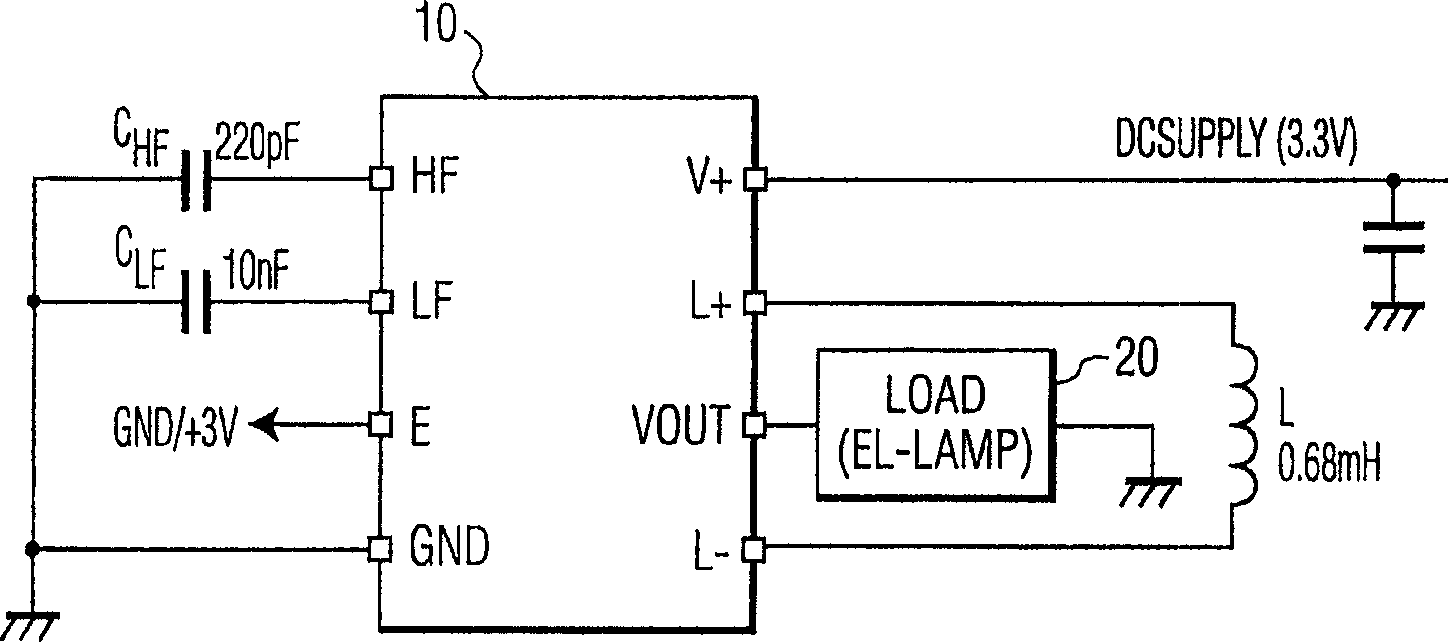
[0020] figure 1 An application of the driver circuit 10 according to one embodiment of the present invention is shown. As shown, the driver circuit 10 provides power to a load, such as an EL lamp 20 . The drive circuit 10 powers the EL lamp by repeatedly charging the inductor L with current from a low voltage DC power supply of about 3.3V and discharging the current to the capacitor of the EL lamp. With each cycle, the voltage of the lamp increases. After a sufficient charge cycle, the lamp will be discharged in a controlled manner and the lamp will be charged again with the opposite polarity. In this way, a symmetrical low frequency voltage is established across the lamp.

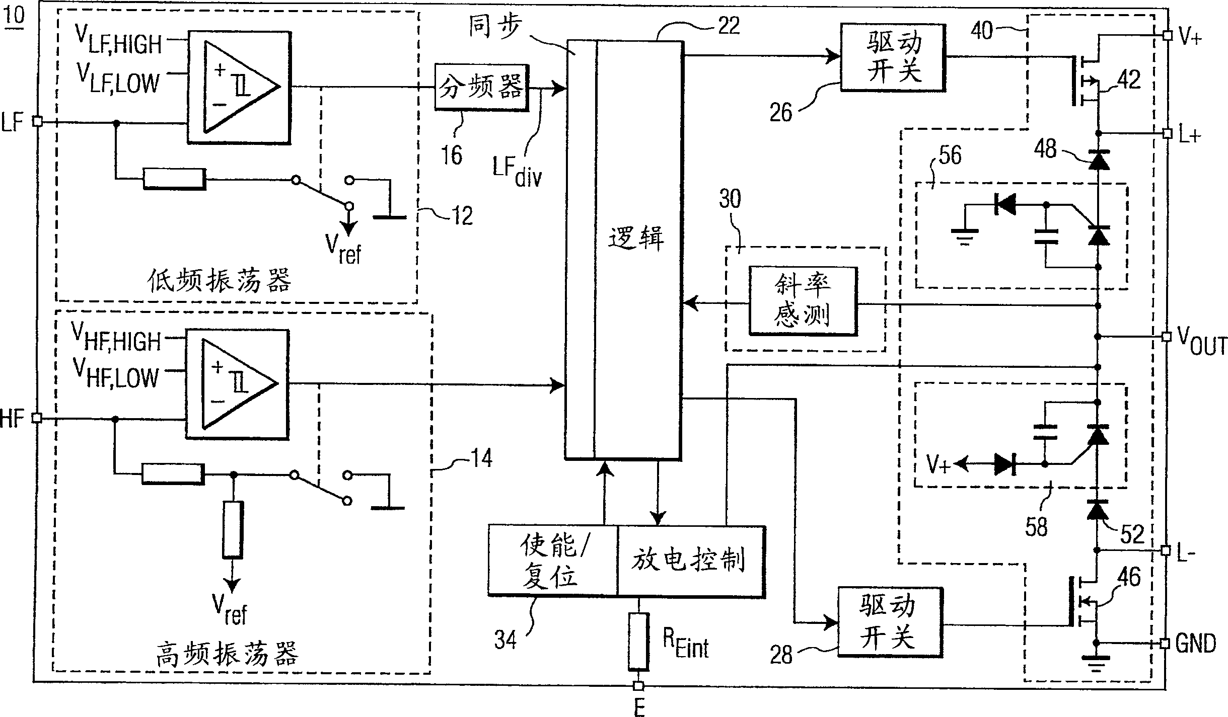
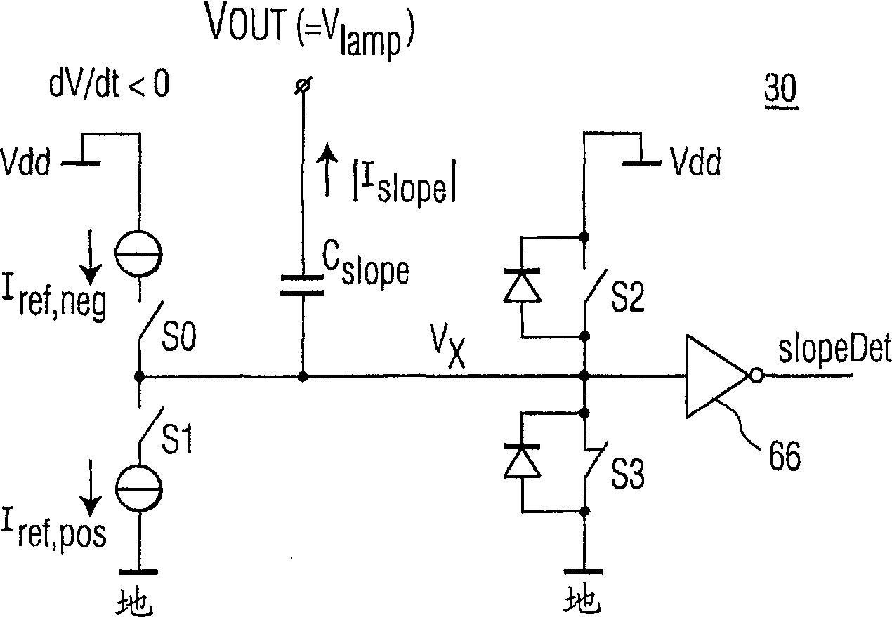
[0021] figure 2 A functional block diagram of the drive circuit 10 according to one embodiment of the present invention is shown. In the drive circuit 10, a low frequency (LF) oscillator 12 provides an LF signal to a controller 22 to control...


PUM


Abstract

The present invention provides a driver circuit with load discharge detection particularly suitable for use with electro-luminescence (EL) lamps. The driver circuit determines the moment at which the load has been discharged by a defined discharge current. This information is used to start the new charging cycle of the load. The discharge time adapts itself to different load sizes or load voltages. Also, a minimum amount of time is used to discharge the load, so that a maximum amount of time is available for charging the load at a predetermined frequency. As a result, a higher performance can be achieved.

Description

Background of the Invention [0001] The present invention relates generally to semiconductor integrated circuit (IC) devices and, more particularly, to driver circuits with load discharge detection, particularly suitable for use with electroluminescence (EL) lamps. [0002] EL lamps are used for backlighting LCD displays in mobile phones and PDAs. EL lamps have consistent brightness along the area of ​​the lamp. This is an advantage compared to backlighting using LEDs, since backlighting using LEDs produces bright spots. Since the EL lamp behaves like a large capacitor, it is driven by an AC voltage of 200-400Hz. The magnitude of the AC voltage (100-250V) determines the brightness. [0003] The driving of the EL lamp plays an important role in ensuring the uniform brightness of the EL lamp. Conventional EL lamp drivers attempt to achieve lamp brightness uniformity in various ways. Some EL lamp drivers, such as the Supertex HV824 available from Supertex in Sunnyvale, Califo...

Claims


Application Information

Patent Timeline
IPC IPC(8): H05B33/14H05B37/02H05B44/00
CPCY02B20/325Y10S315/02H05B33/08Y02B20/30H05B44/00
Inventor B·费尔赫文A·格拉基斯特
Owner NXP BV
Why Eureka
Try Eureka