
Rotation angle sensor

A technology of rotation angle and sensor, which is applied in the direction of converting sensor output, measuring angle, angle/taper measurement, etc. It can solve the problems of difficult compactness, high manufacturing cost, complex structure, etc., and achieve the effect of reducing size and low manufacturing cost

Inactive Publication Date: 2005-08-31
DENSO CORP
View PDF0 Cites 16 Cited by
  • Summary
  • Abstract
  • Description
  • Claims
  • Application Information

AI Technical Summary

Problems solved by technology

[0005] In addition, the rotation angle sensor using the Hall element not only uses an expensive Hall element, but also has a complex structure, so its manufacturing cost is high
Also, it is difficult to make a rotation angle sensor using a Hall element more compact because it uses a magnet.

Method used


Image

  • Rotation angle sensor
  • Rotation angle sensor
  • Rotation angle sensor

Examples


no. 1 example

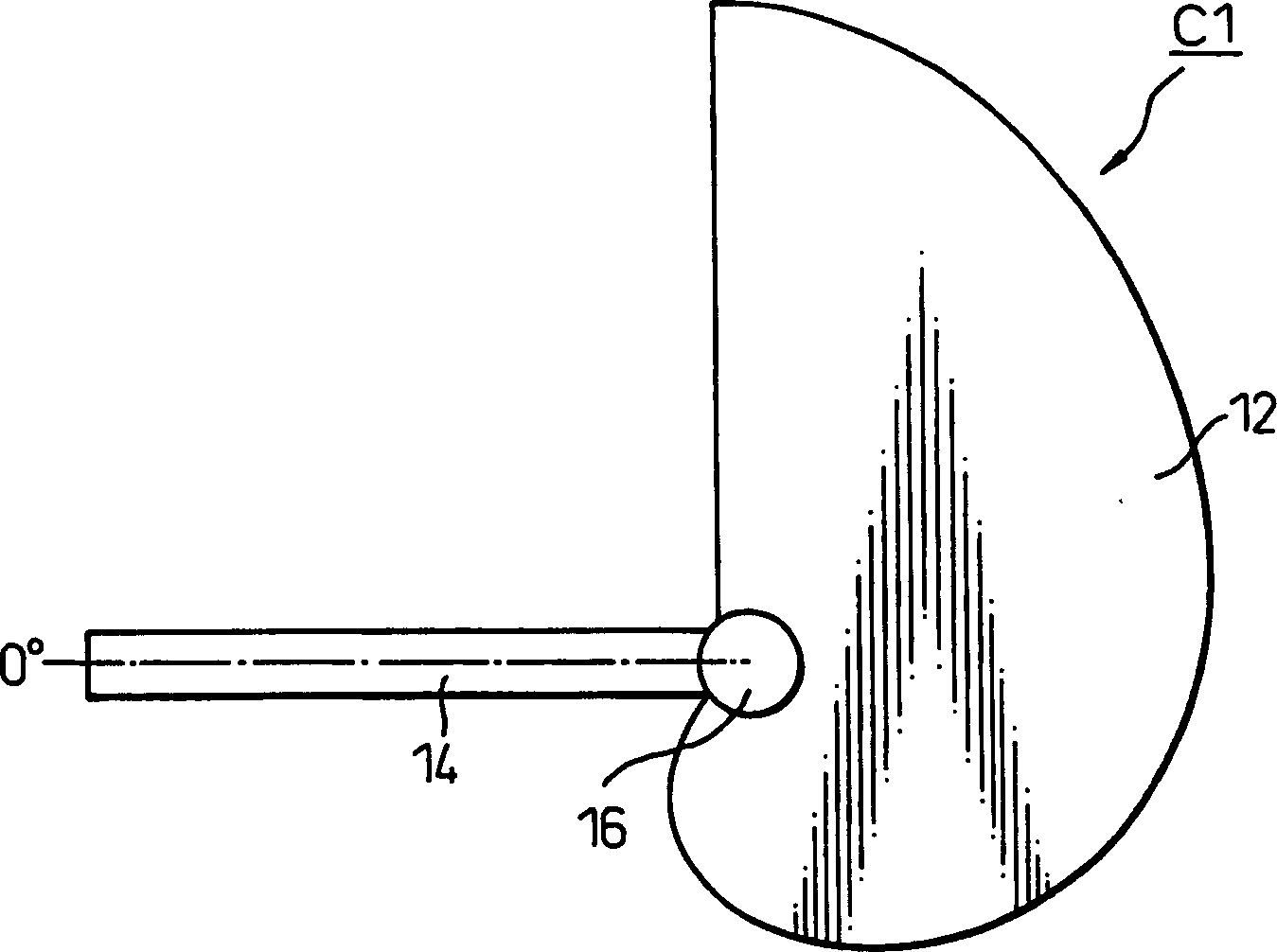
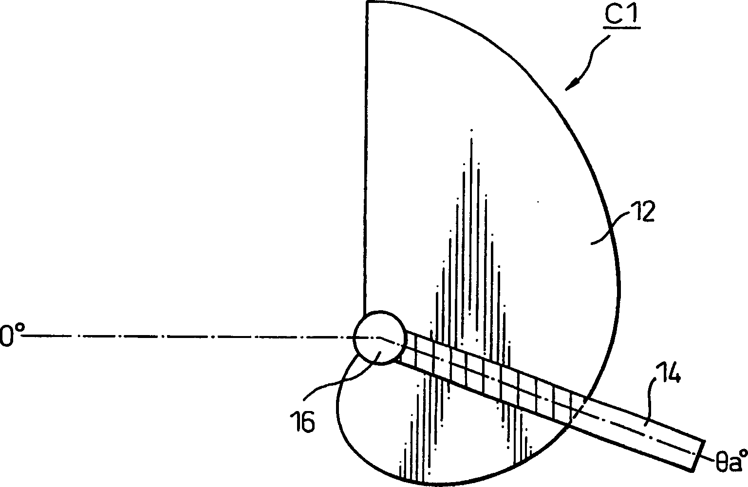
[0025] FIG. 1A is a plan view of a schematic configuration of a rotation angle sensor 10 of a first embodiment of the present invention. Figure 1B and Figure 2A and 2B is a front view of the rotation angle sensor 10 . The rotation angle sensor 10 includes a variable capacitor C1 and a C-V (capacitance-voltage) conversion circuit 20 .

[0026] Construction and Operation of Variable Capacitors

[0027] The variable capacitor C1 includes a fixed electrode 12 , a movable electrode 14 and a shaft 16 . Furthermore, the variable capacitor C1 is fabricated using a micromachining technique. From Figure 1B and Figure 2A and 2B The vertical and horizontal external dimensions of the variable capacitor C1 are both less than 1 mm when viewed from the front view direction shown in .

[0028] The planar fixed electrode 12 has a cylindrical axis 16 rotatable in a direction perpendicular to its surface. An elongated movable electrode 14 is fastened on this shaft 16 . Also, the mov...

no. 2 example

[0056] 6A is a plan view of a schematic configuration of a rotation angle sensor 30 of the second embodiment, and Figure 6B is a front view of the rotation angle sensor 30 . The rotation angle sensor 30 differs from the rotation angle sensor 10 of the first embodiment only in the planar shape of the fixed electrode 22 of the variable capacitor C1.

[0057] Figure 7 is a graph of the relationship between the rotation angle of the movable electrode 14 and the electrostatic capacitance between the electrodes 12 and 14 in the second embodiment. The planar shape of the fixed electrode 22 is set so that the electrostatic capacity between the electrodes 12 and 14 (the area of ​​the overlapped portion of the electrodes 12 and 14) is determined according to Figure 7 The characteristics shown in can vary.

[0058] Thus, in the second embodiment, by appropriately setting the planar shape of the fixed electrode 22, the electrostatic capacitance between the electrodes 12 and 14 can b...


PUM


Abstract

A rotation angle sensor including a variable capacitor and a C-V converting circuit, wherein the variable capacitor has a detected object fastened and fixed to its shaft, a planar shape of a movable electrode is set so that an area of overlapping parts of electrodes changes linearly with respect to a change of the rotation angle of the movable electrode, a voltage signal of the C-V converting circuit corresponds to the change of the electrostatic capacity of the variable capacitor with respect to the fixed capacitor, and consequently the voltage signal of the C-V converting circuit (detection signal) can be made to change linearly with respect to broad changes of the rotation angle of the detected object (0 DEG to 270 DEG ).

Description

technical field [0001] The invention relates to a rotation angle sensor, in particular to a rotation angle sensor for detecting the rotation angle of a measured object. Background technique [0002] In the past, widely used rotation angle sensors were equipped with magnets and Hall elements. The magnets were installed on the object whose rotation angle was to be detected and rotated together with the object to be measured. in the magnetic field, and output a voltage corresponding to the magnetic field strength, and each Hall element outputs an output voltage of the Hall element as a signal representing the rotation angle of the measured object (for example, see Japanese Unexamined Patent Publication (Kokai) No. 2000-329513 (pages 2 to 10, Fig. 4 and Figure 5 ), the output voltage of the Hall element varies with the change of the angle between the magnetic field direction of the magnet and the magnetically sensitive surface of the Hall element. Such a rotation angle sensor ...

Claims


Application Information

Patent Timeline
Patent Type & Authority Applications(China)
IPC IPC(8): G01D5/24G01B7/30G01C1/00G01D5/14G01D5/241G01R27/26
CPCG01D5/2412G01B7/30G01B7/24G01D5/145G01B5/24G01R27/2605
Inventor 惠岛贵志牧野泰明山内重德
Owner DENSO CORP
Learn More