Ferrite material

A technology of ferrite material and sintered body, applied in the direction of magnetic material, inorganic material magnetic, iron compound, etc., can solve the problem of not being able to have both the saturation magnetic flux density and so on

Inactive Publication Date: 2005-08-31
TDK CORPARATION
View PDF4 Cites 22 Cited by
  • Summary
  • Abstract
  • Description
  • Claims
  • Application Information

AI Technical Summary

Problems solved by technology

The ferrite materials disclosed in Japanese Patent Laid-Open No. 6-310321 and Japanese Patent Laid-Open No. 11-3813 cannot have both the characteristics of saturation magnetic flux density and low loss in high-temperature regions.

Method used


Image

  • Ferrite material
  • Ferrite material
  • Ferrite material

Examples


no. 1 Embodiment

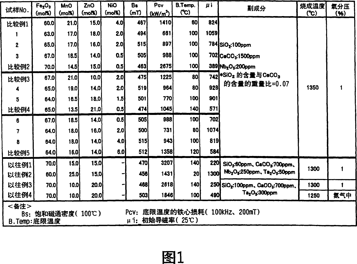
[0077] Experiments conducted to confirm a preferable composition of MnZnNi-based ferrite are shown as a first example.

[0078] A ferrite with the composition shown in Figure 1 was fabricated.

[0079] As the raw material of the main component, Fe is used 2 o 3 powder, MnO powder, ZnO powder and NiO powder. These powders were calcined at 900° C. for 2 hours after wet mixing.

[0080] Next, the calcined product of the raw material of the main component and the raw material of the subcomponent are mixed. SiO is used as a raw material for subcomponents 2 Powder, CaCO 3 powder and Nb 2 o 5 powder. The raw material of the subcomponent is added to the calcined product of the raw material of the main component, and mixed while pulverizing. Pulverization was performed until the average particle diameter of the calcined product became 1.5 μm. A binder was added to the obtained mixture, and it was granulated and molded to obtain a ring-shaped molded body.

[0081] The obtaine...

no. 2 Embodiment

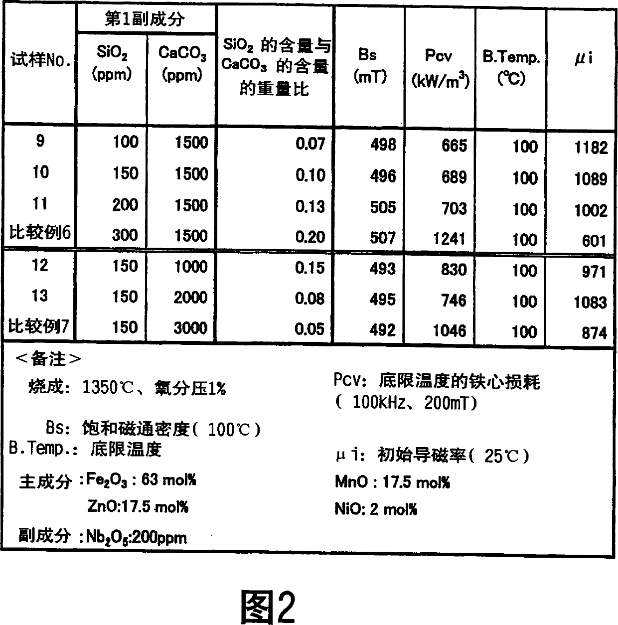
[0091] An experiment conducted to confirm the optimum addition amount of the first subcomponent for MnZnNi-based ferrite is shown as a second example.

[0092] A ferrite core having the composition shown in FIG. 2 was produced by the same process as in the first embodiment. In addition, magnetic properties and the like were measured under the same conditions as in the first example. The results are shown together in FIG. 2 .

[0093] As shown in FIG. 2 , it can be seen that the core loss (Pcv) can be reduced by adding Si and Ca as the first subcomponents in predetermined amounts. However, in the case of Si, the amount added is SiO 2 When converted to 300ppm, the core loss increases. On the other hand, in the case of Ca, its addition amount is expressed as CaCO 3 When converted into an additive amount of 3000 ppm, the core loss increases.

no. 3 Embodiment

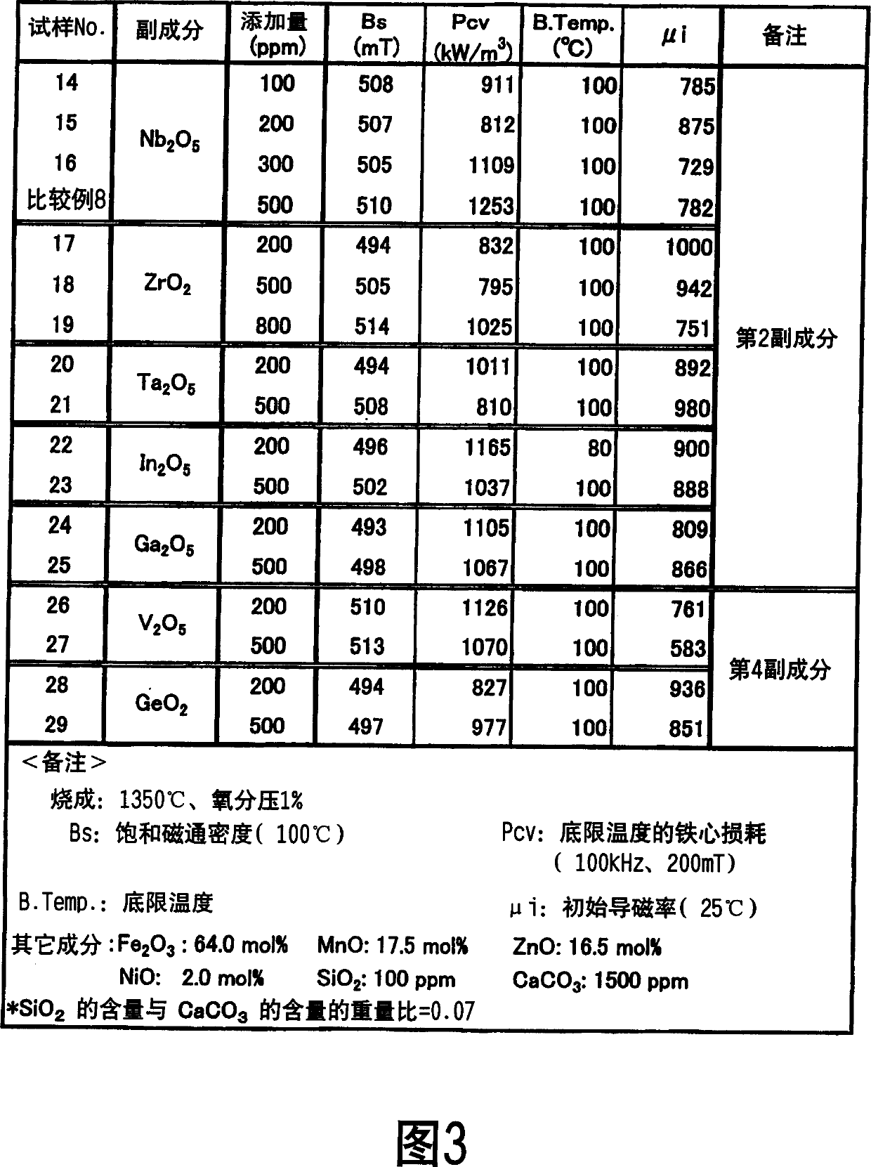
[0095] An experiment conducted to confirm changes in magnetic properties and the like associated with the addition of the second subcomponent or the fourth subcomponent for MnZnNi-based ferrite is shown as a third example.

[0096] A ferrite core having the composition shown in FIG. 3 was produced by the same process as in the first embodiment. In addition, magnetic properties and the like were measured under the same conditions as in the first example. The results are shown together in FIG. 3 .

[0097] As shown in Figure 3, it can be seen that even if the second subcomponent (Nb 2 o 5 , ZrO 2 、 Ta 2 o 5 、In 2 o 5 , Ga 2 o 5 ) or the fourth subcomponent (V 2 o 5 、GeO 2 ) still has a saturation magnetic flux density (Bs) of around 500mT, while obtaining 1200kW / m 3 or less core loss (Pcv). Nb in the second subcomponent 2 o 5 , ZrO 2 、 Ta 2 o 5 , and GeO in the fourth subcomponent 2 The effect of reducing the core loss is greater. For its Nb 2 o 5 In other...


PUM

PropertyMeasurementUnit
saturation flux densityaaaaaaaaaa
particle sizeaaaaaaaaaa

Abstract

A Mn-Zn based ferrite sintered body containing 62 to 68 mol% of Fe2O3 and 12 to 20 mol% of ZnO is made to contain, as main constituents, NiO and / or LiO0.5. Additionally, a Mn-Zn based ferrite sintered body containing 62 to 68 mol% of Fe2O3 and 12 to 23 mol% of ZnO is made to contain, as additives, Si and Ca. This sintered body can achieve such properties that the saturation magnetic flux density at 100 DEG C is 450 mT or more (magnetic field for measurement: 1194 A / m), the minimum core loss value is 1200 kW / m<3> or less (measurement conditions: 100 kHz, 200 mT), the bottom temperature at which the minimum core loss value is exhibited is from 60 to 130 DEG C, and the initial permeability at room temperature is 700 or more.

Description

technical field [0001] The present invention relates to ferrite materials suitable for electronic components such as transformers, reactors, and choke coils. Background technique [0002] In recent years, miniaturization and higher output of electronic devices have progressed, and along with higher integration of various components and higher processing speeds, higher currents have been demanded for power supply lines that supply power. [0003] Also, a power cord capable of maintaining a set performance even at a high temperature is required because the power cord is exposed to heat generated by components such as a CPU or the like. In addition, it is necessary for the power cord to maintain the set performance under the condition of high ambient temperature such as electronic circuits for automobiles. [0004] Therefore, transformers and reactors used in power lines are required to be able to use large currents even at high temperatures. [0005] As materials for these t...

Claims


Application Information

Patent Timeline
Patent Type & Authority Applications(China)
IPC IPC(8): C01G49/00C04B35/26C04B35/38H01F1/34H01F1/36
CPCC04B2235/3239C04B2235/3293C04B2235/3232H01F1/36C04B35/265C04B2235/77C04B2235/3294C04B2235/3279C04B2235/6584C04B2235/3203C04B2235/3262C04B2235/3287C01P2006/42C04B2235/3298C04B2235/3418C04B35/2616C04B2235/3284C01G49/0018C01P2006/40C04B2235/42C04B2235/3208C04B2235/3286C04B2235/727C04B2235/3251H01F1/344C04B2235/786C04B2235/447C04B2235/656C04B2235/3256C04B2235/3244C04B35/26
Inventor 高川建弥福地英一郎村濑琢
Owner TDK CORPARATION
Why Eureka
Try Eureka