
Internal combustion engine controller

An internal combustion engine and controller technology, which is applied in the directions of engine control, fuel injection control, electrical control, etc., can solve problems such as reducing the efficiency of internal combustion engines

Inactive Publication Date: 2005-09-07
TOYOTA JIDOSHA KK
View PDF1 Cites 0 Cited by
  • Summary
  • Abstract
  • Description
  • Claims
  • Application Information

AI Technical Summary

Problems solved by technology

This reduces the efficiency of the internal combustion engine

Method used


Image

  • Internal combustion engine controller
  • Internal combustion engine controller
  • Internal combustion engine controller

Examples


Embodiment Construction

[0019] A controller for an internal combustion engine according to a preferred embodiment of the present invention will be described below. In a preferred embodiment, the internal combustion engine is a four-cylinder gasoline engine.

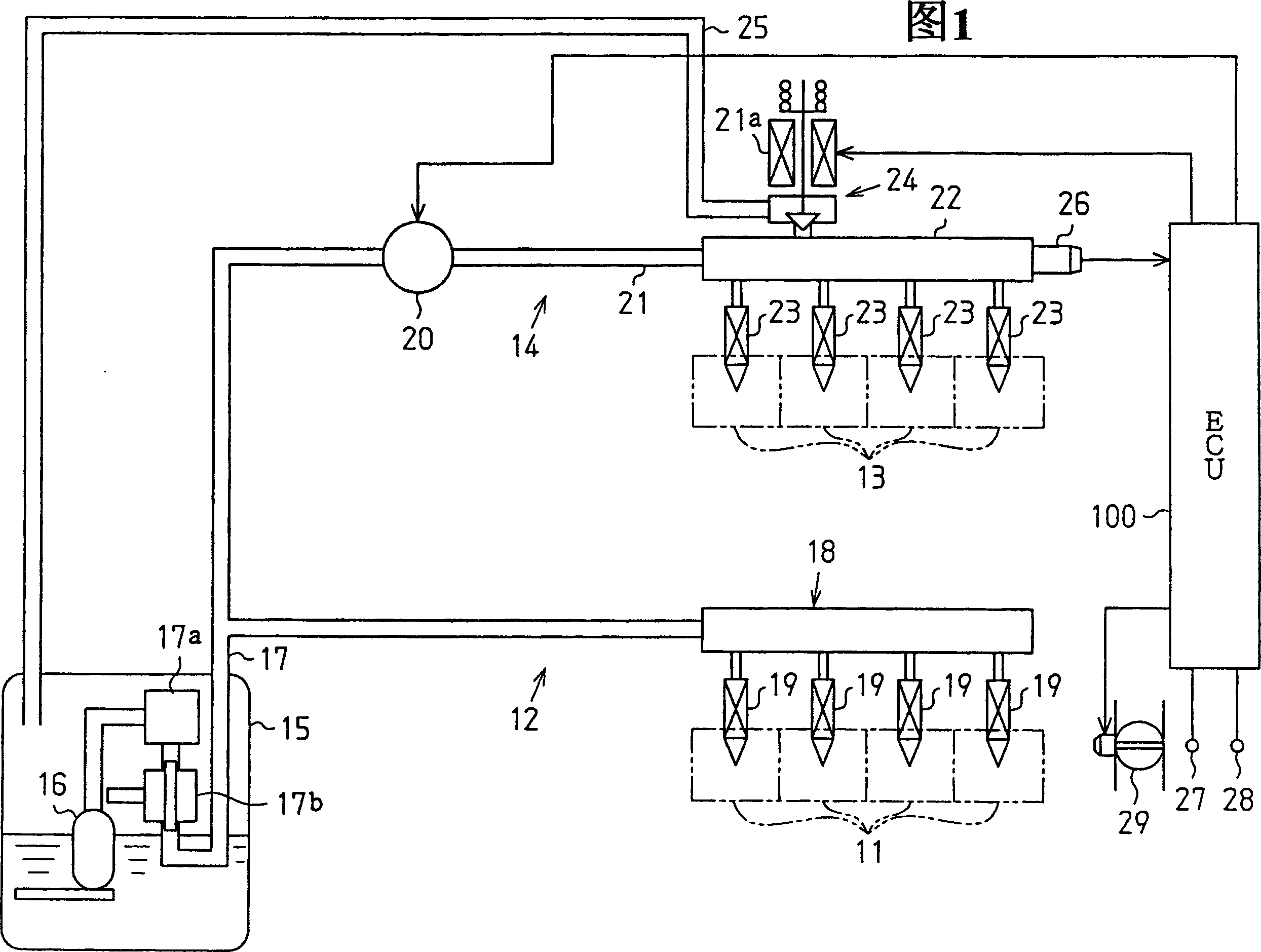
[0020] As shown in FIG. 1, the fuel circulation system of an internal combustion engine includes: a low-pressure fuel system 12, which injects fuel into the intake port 11 of the intake passage; and a high-pressure fuel system 14, which injects fuel directly into the combustion chamber 13.

[0021] The low-pressure fuel system 12 includes a fuel tank 15 that holds fuel and a feed pump 16 (low-pressure pump) that draws the fuel. The fuel feed pump 16 draws out fuel and feeds the fuel to a low-pressure distribution pipe 18 (low-pressure pipe) through a filter 17a and a pressure regulator 17b arranged in a low-pressure fuel passage 17 . The filter 17a filters fuel. The pressure regulator 17 b regulates the fuel pressure in the low-pressure fuel p...


PUM


Abstract

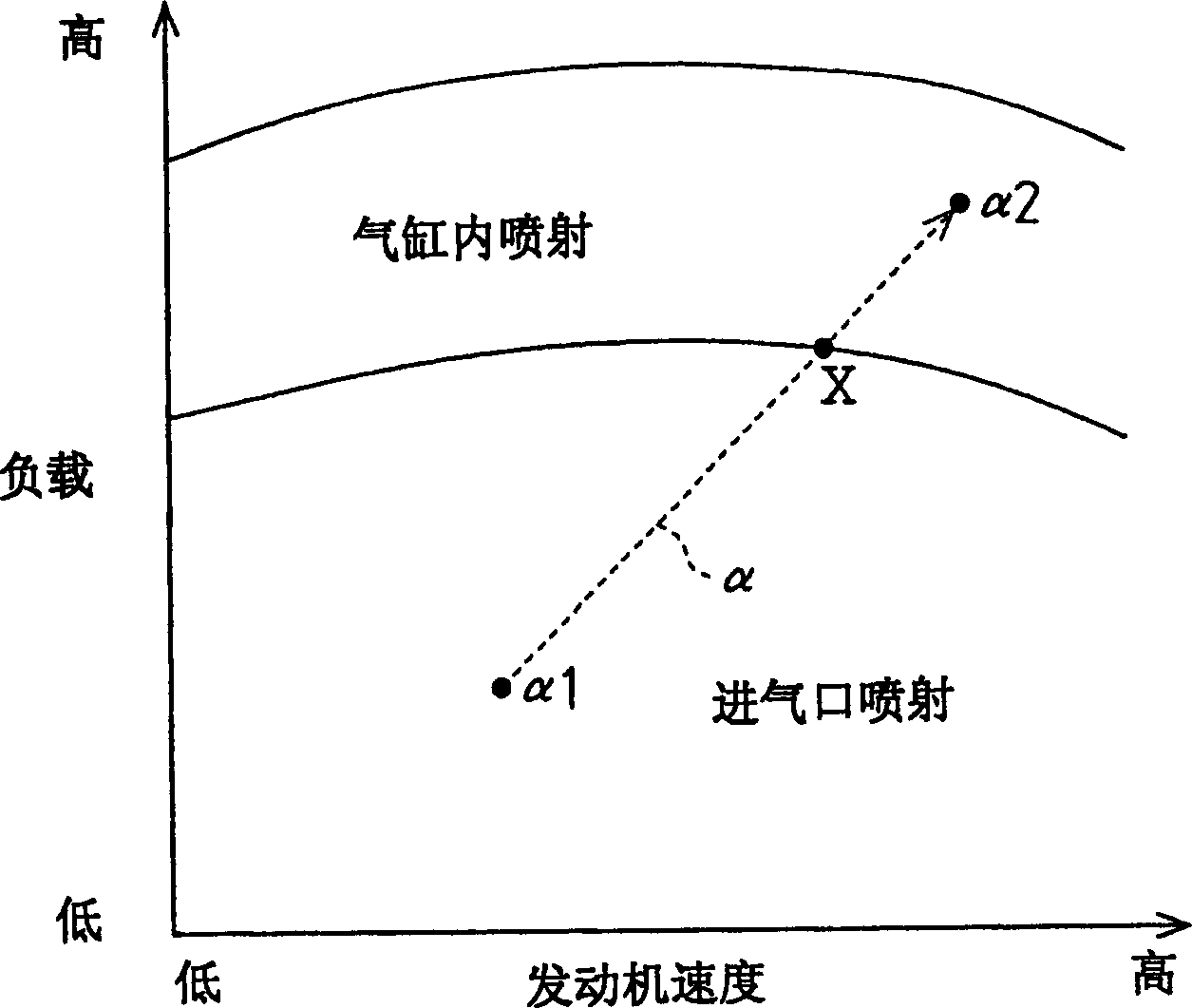
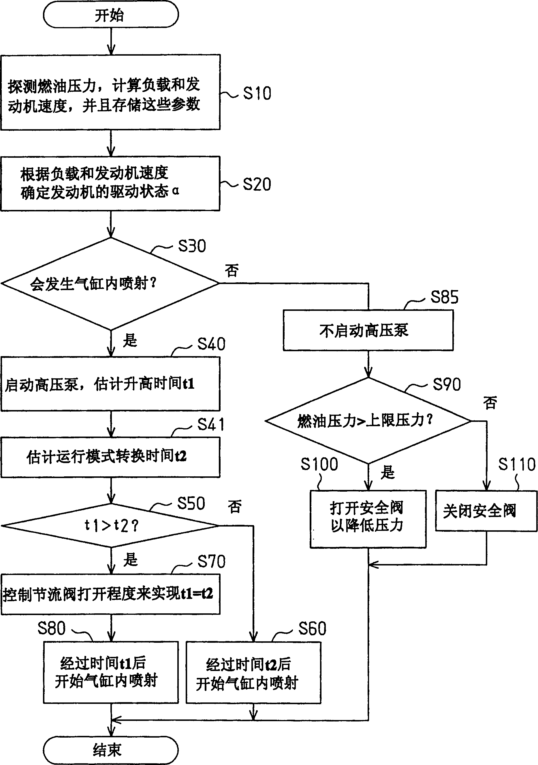
An ECU for an internal combustion engine predicts change in the driving state of the engine when switching from port injection mode to in-cylinder injection mode. In accordance with the prediction, the ECU actuates a high-pressure pump before entering the in-cylinder injection mode to pressurize the fuel supplied to an air-intake passage injector.

Description

technical field [0001] This invention relates to controls for regulating the pressure of high pressure fuel supplied to in-cylinder injectors of internal combustion engines. Background technique [0002] Japanese Laid-Open Patent Publication No. 7-103048 discloses a conventional controller of an internal combustion engine. A conventional controller-controlled internal combustion engine includes an in-cylinder injector and an intake passage injector for each cylinder of the internal combustion engine. More specifically, when injecting fuel into the combustion chamber in each cylinder, the controller uses an appropriate one of the above two injectors according to the engine driving state of the internal combustion engine such as engine load and engine speed. [0003] When fuel is injected from an in-cylinder injector (in-cylinder injector mode), fuel having a high pressure (required fuel pressure) must be supplied to a high-pressure distribution pipe connected to the in-cylin...

Claims


Application Information

Patent Timeline
Patent Type & Authority Applications(China)
IPC IPC(8): F02D1/02F02D41/04F02D41/38F02D45/00F02M59/20F02M69/04
CPCF02M63/029F02D2041/3881F02D41/3094F02M69/046F02D41/3845F02D2041/1412
Inventor 坂井光人山崎大地秋田龙彦仓田尚季
Owner TOYOTA JIDOSHA KK
Learn More