Methods and system for automatically stopping an engine

a technology of automatic stopping and engine, applied in the direction of braking system, engine starter, electric control, etc., can solve the problems of reducing engine fuel efficiency, storing large amounts of vacuum, and human drivers may find the vehicle more difficult to stop, so as to achieve the desired level of fuel efficiency, reduce engine fuel efficiency, and save fuel

Inactive Publication Date: 2020-08-20
FORD GLOBAL TECH LLC
View PDF0 Cites 1 Cited by
  • Summary
  • Abstract
  • Description
  • Claims
  • Application Information

AI Technical Summary

Benefits of technology

[0002]A vehicle's engine may be automatically stopped when the vehicle is moving, but stopping the engine deactivates a motive power source for the vehicle brakes. In particular, the engine may provide vacuum to assist a human driver that is applying the vehicle's brakes. If the engine is stopped and a brake booster vacuum level is low, the human driver may experience a “hard pedal” before the vehicle is stopped. The “hard pedal” condition may be objectionable to the human driver and the human driver may find the vehicle to be more difficult to stop. One way to reduce the possibility of a human driver experiencing a “hard pedal” condition is to prevent the engine from stopping until the vehicle is at rest. However, opportunities to conserve fuel may be lost if the engine is restricted to stopping only when the vehicle is at rest. Another way of reducing the possibility of a human driver experiencing a “hard pedal” condition may be to store a large amount of vacuum in a vacuum reservoir, but storing large amounts of vacuum may decrease engine fuel efficiency. Therefore, it may be desirable to provide a way of stopping the engine that reduces the possibility of a human driver experiencing “hard pedal” conditions, yet delivers a desired level of fuel efficiency.

Problems solved by technology

The “hard pedal” condition may be objectionable to the human driver and the human driver may find the vehicle to be more difficult to stop.
However, opportunities to conserve fuel may be lost if the engine is restricted to stopping only when the vehicle is at rest.
Another way of reducing the possibility of a human driver experiencing a “hard pedal” condition may be to store a large amount of vacuum in a vacuum reservoir, but storing large amounts of vacuum may decrease engine fuel efficiency.
Further, the engine may be stopped when the vehicle is stopped even though the brake booster vacuum level may be lower since the vehicle may remain stopped even when only a small amount of vacuum is available.

Method used


Image

  • Methods and system for automatically stopping an engine
  • Methods and system for automatically stopping an engine
  • Methods and system for automatically stopping an engine

Examples


Embodiment Construction

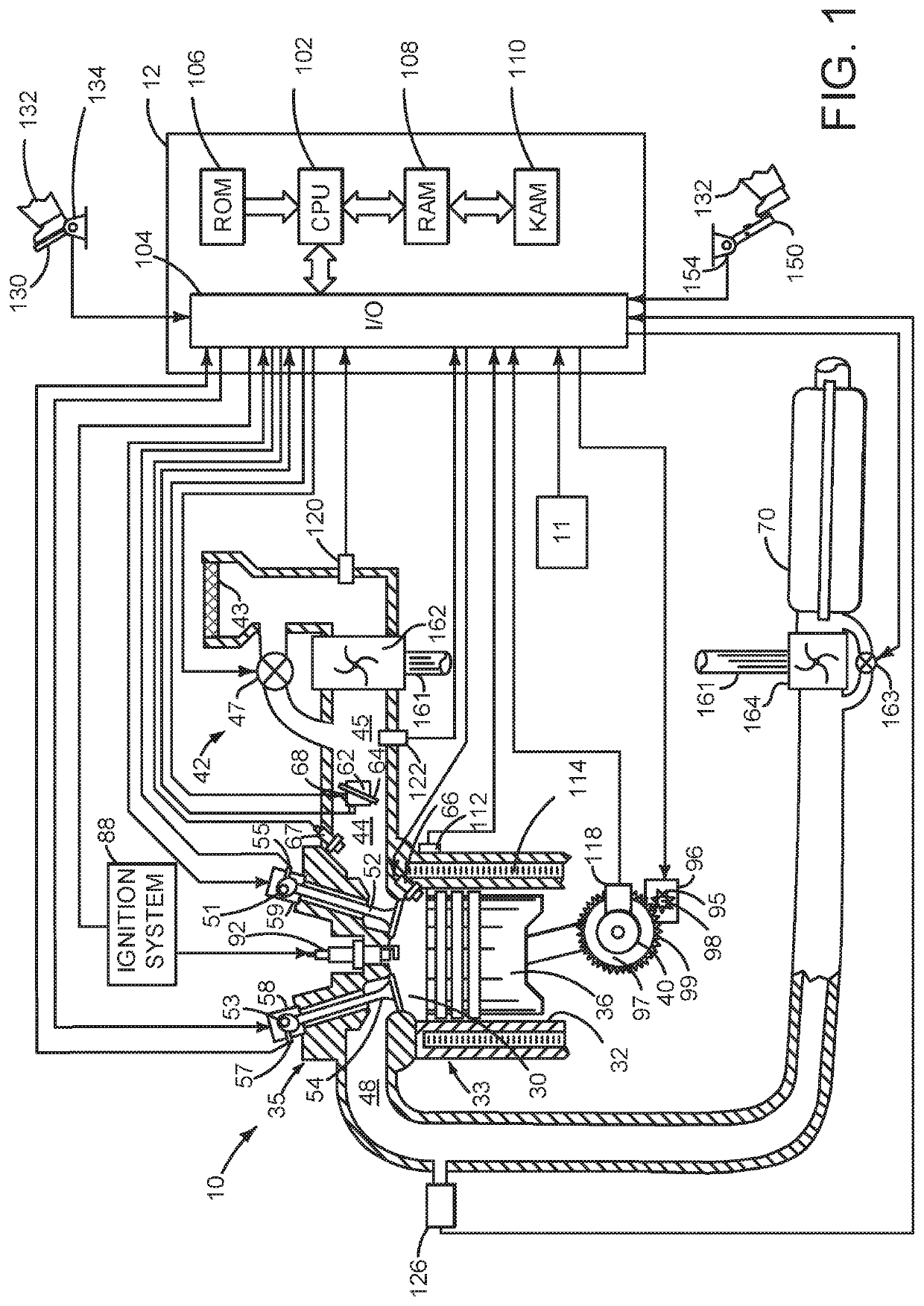
[0014]The present description is related to operating a vehicle that includes an engine that may be automatically stopped (e.g., the engine may be stopped in response to vehicle operating conditions via a controller without a human or autonomous driver specifically requesting an engine stop via a dedicated input that has sole function(s) for stopping and starting the engine, such as a pushbutton or key switch) and automatically started (e.g., the engine may be started in response to vehicle operating conditions via a controller without a human or autonomous driver specifically requesting an engine start via a dedicated input that has sole function(s) for stopping and starting the engine, such as a pushbutton or key switch). The approach may dynamically adjust a vacuum boost threshold vacuum level responsive to vehicle speed so that a desired amount of braking assist may be made available without having to store excess vacuum. The vehicle may include an engine of the type shown in FI...


PUM


Abstract

Systems and methods for operating a vehicle that includes an engine that may be automatically stopped and started are described. In one example, an engine may be automatically stopped in response to a brake booster vacuum threshold level that is adjusted responsive to vehicle speed so that opportunities to automatically stop an engine may be increased, thereby conserving fuel.

Description

FIELD[0001]The present description relates to methods and a system for a vehicle that includes an engine that may be automatically stopped and started.BACKGROUND AND SUMMARY[0002]A vehicle's engine may be automatically stopped when the vehicle is moving, but stopping the engine deactivates a motive power source for the vehicle brakes. In particular, the engine may provide vacuum to assist a human driver that is applying the vehicle's brakes. If the engine is stopped and a brake booster vacuum level is low, the human driver may experience a “hard pedal” before the vehicle is stopped. The “hard pedal” condition may be objectionable to the human driver and the human driver may find the vehicle to be more difficult to stop. One way to reduce the possibility of a human driver experiencing a “hard pedal” condition is to prevent the engine from stopping until the vehicle is at rest. However, opportunities to conserve fuel may be lost if the engine is restricted to stopping only when the ve...

Claims


Application Information

Patent Timeline
Patent Type & Authority Applications(United States)
IPC IPC(8): F02D41/04B60T13/52B60T13/72B60T13/66
CPCB60T13/72B60T2230/04F02D41/042F02D2200/602B60T7/042B60T13/52F02D2200/501B60T13/662B60W10/02B60W10/06B60W10/08B60W10/184B60W30/18018B60W2510/18B60W2520/10F02D29/02F02D2200/60F02N11/0803F02N11/084F02N2200/0801F02N2200/0807F02N2200/102Y02T10/40
Inventor KHAFAGY, HAFIZFERGUSON, RUSSKUCUKARSLAN, DAVUD
Owner FORD GLOBAL TECH LLC
Why Eureka
Try Eureka