Backlight system

A technology of backlight and light guide plate, which is applied in the direction of lighting devices, fixed lighting devices, components of lighting devices, etc., and can solve problems such as sense of difference

Inactive Publication Date: 2005-09-07
CITIZEN ELECTRONICS CO LTD
View PDF2 Cites 8 Cited by
  • Summary
  • Abstract
  • Description
  • Claims
  • Application Information

AI Technical Summary

Problems solved by technology

In an LCD using a backlight device in which the directionality of light in the longitudinal direction of the backlight device is different from that in the width direction of the backlight device, there is a problem such as a sense of difference due to a difference in brightness.

Method used


Image

  • Backlight system
  • Backlight system
  • Backlight system

Examples


Embodiment Construction

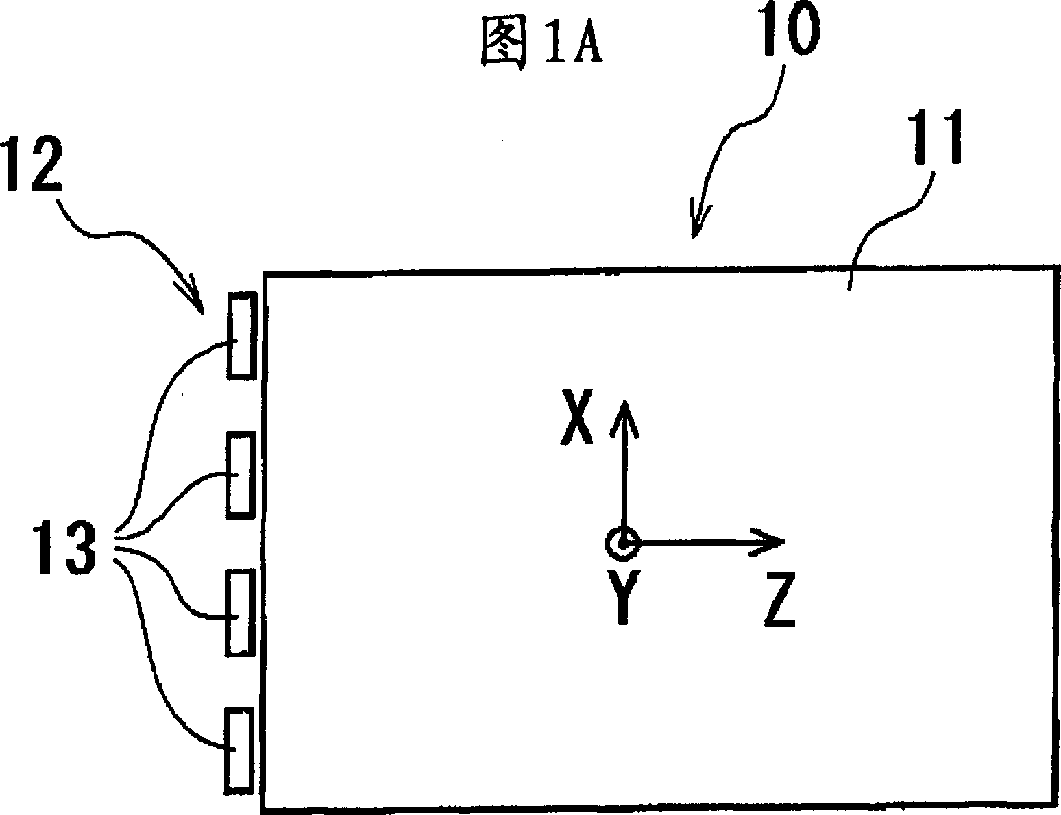
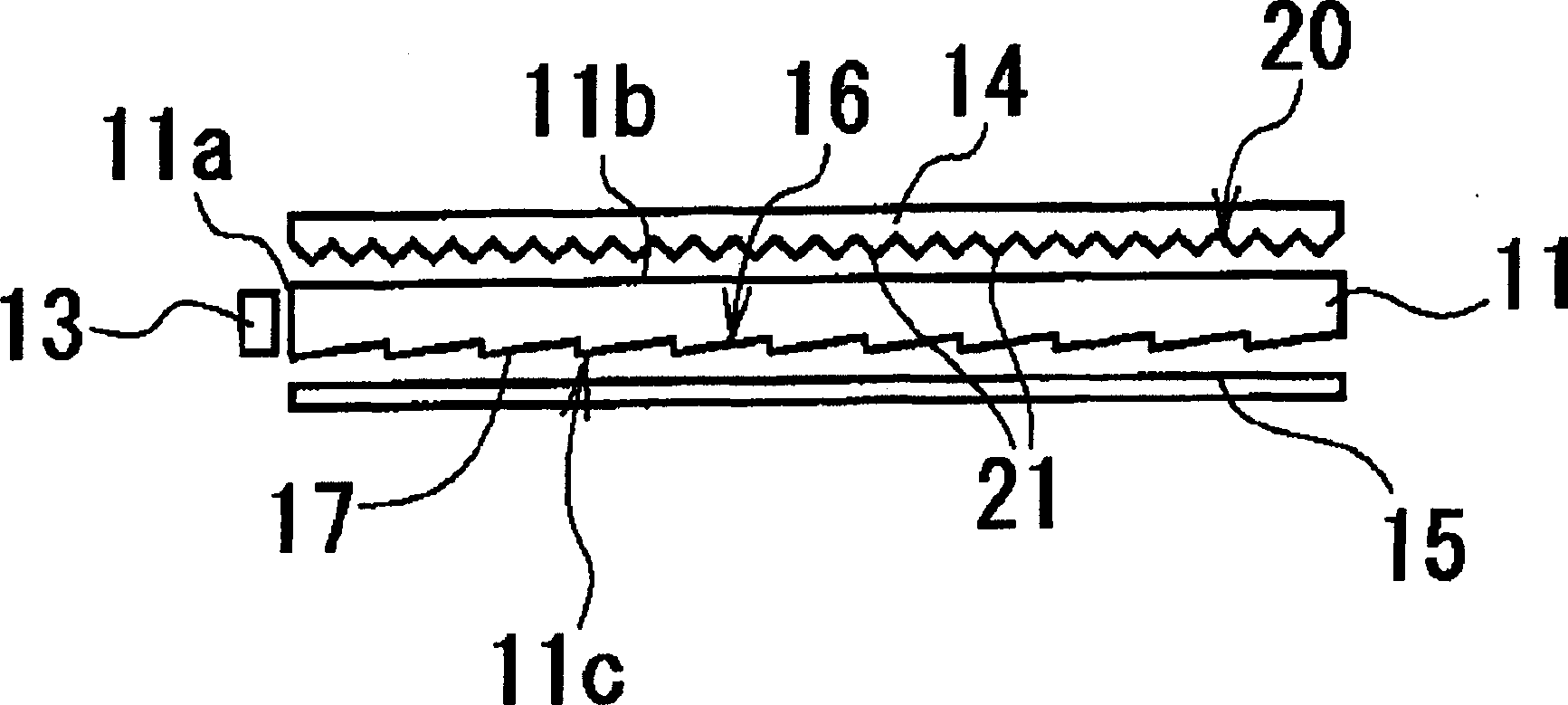
[0018] Hereinafter, preferred embodiments of the present invention will be described in detail with reference to the accompanying drawings. Referring to Figure 1A and Figure 1B , shows a backlight device 10 according to an embodiment of the present invention. The backlight device 10 includes a light guide plate 11 and a light source 12 that irradiates light onto the light guide plate 11 . In the illustrated embodiment, the light source 12 is composed of a plurality of light-emitting diodes (LEDs) 13, which are close to the incident surface 11a formed on one side of the light guide plate 11, and these LEDs 13 are arranged at intervals along the incident surface 11a. .

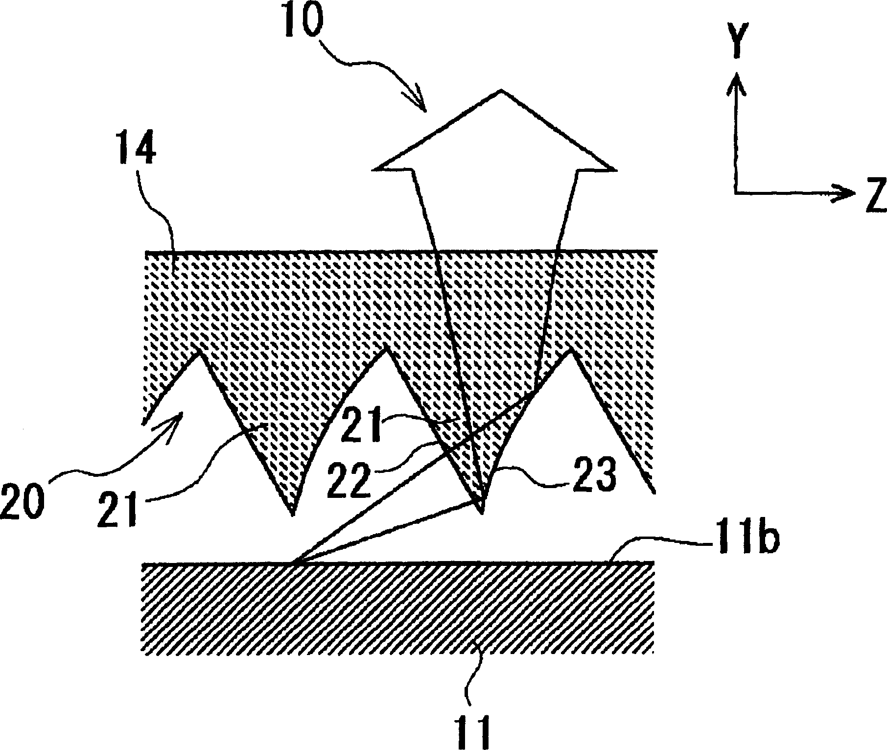
[0019] In addition, the prism plate 14 is disposed opposite to and close to the upper surface 11 b of the light guide plate 11 , and the reflection plate 15 is disposed opposite to and close to the lower surface 11 c of the light guide plate 11 .

[0020] In addition, in FIG. 1A, X represents the width direct...


PUM


Abstract

A backlight system comprising a light-guiding plate having a light-entrance surface, an upper surface, and a lower surface, a light source disposed to face the light-entrance surface, a reflecting sheet disposed to face the lower surface of the light-guiding plate, a prismatic sheet disposed to face the upper surface of the light-guiding plate, and a micro-prismatic mechanism provided on the lower surface of the prismatic sheet, the micro-prismatic mechanism including a plurality of projection-like prismatic parts extending parallel to the light-entrance surface of the light-guiding plate and disposed at intervals in a generally perpendicular direction to the light-entrance surface, each prismatic part having a pair of prismatic surfaces, of each pair of prismatic surfaces, at least the prismatic surface on the side further from the light source forming into a curved surface.

Description

technical field [0001] The present invention relates to a backlight device for backlighting a small liquid crystal display used in a mobile phone, a PDA, or the like. Background technique [0002] In recent years, in backlight devices for illuminating small liquid crystal displays (hereinafter referred to as LCDs) such as mobile phones and PDAs, while reducing costs, high brightness, high viewing angle, thin, light weight, and low power consumption are required. Quantities, etc. put forward more stringent requirements. As a light source of such a backlight device, light emitting diodes (hereinafter, simply referred to as LEDs) that consume less power and generate less heat are used. The light emitted from the LED first enters the side of the light guide plate, and is transmitted after being repeatedly reflected in the light guide plate. Next, the light emitted from the lower surface of the light guide plate to the outside is reflected by the reflector and returned to the i...

Claims


Application Information

Patent Timeline
Patent Type & Authority Applications(China)
IPC IPC(8): G02F1/13357F21S8/04F21V5/02F21V7/04F21V8/00F21Y101/02G02B6/00G02F1/1335
CPCG02B6/0038G02B6/0053G02F1/1335
Inventor 宫下纯司渡边清一
Owner CITIZEN ELECTRONICS CO LTD
Why Eureka
Try Eureka