Electromechanical furniture drive mechanism

A transmission device and furniture technology, applied in the direction of electromechanical devices, household appliances, electric components, etc., can solve problems such as change, and achieve the effects of simple manufacturing, solid structure and low cost

Inactive Publication Date: 2005-09-07
斯摩系统股份公司
View PDF4 Cites 0 Cited by
  • Summary
  • Abstract
  • Description
  • Claims
  • Application Information

AI Technical Summary

Problems solved by technology

[0005] With regard to the known furniture transmissions, when adjusting, the angular position of the turning lever changes relative to the linear motion axis movement of the transmission mechanism, which creates a disadvantage: namely, the effective length of the lever arm in contact with the turning axis

Method used


Image

  • Electromechanical furniture drive mechanism
  • Electromechanical furniture drive mechanism
  • Electromechanical furniture drive mechanism

Examples


Example Embodiment

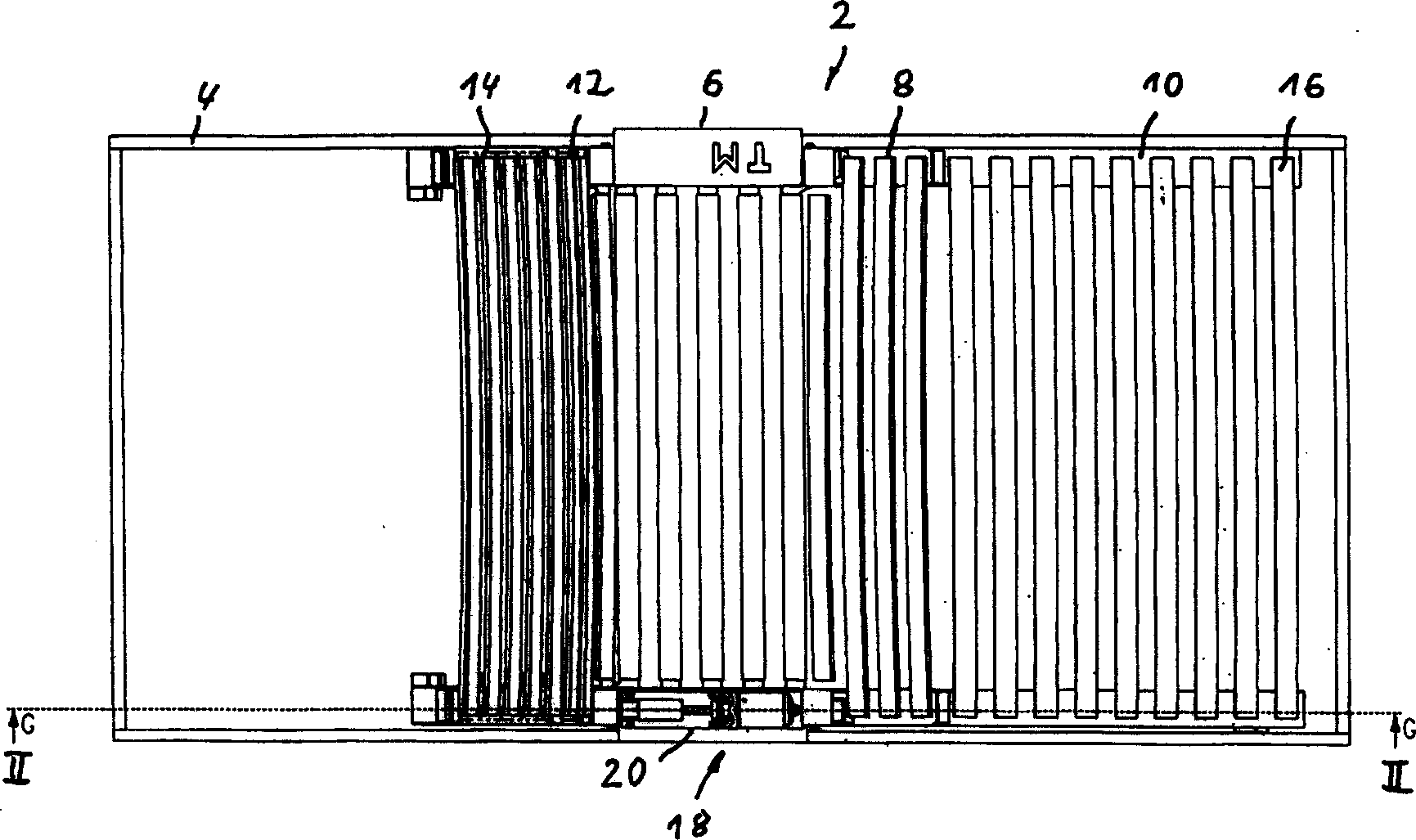
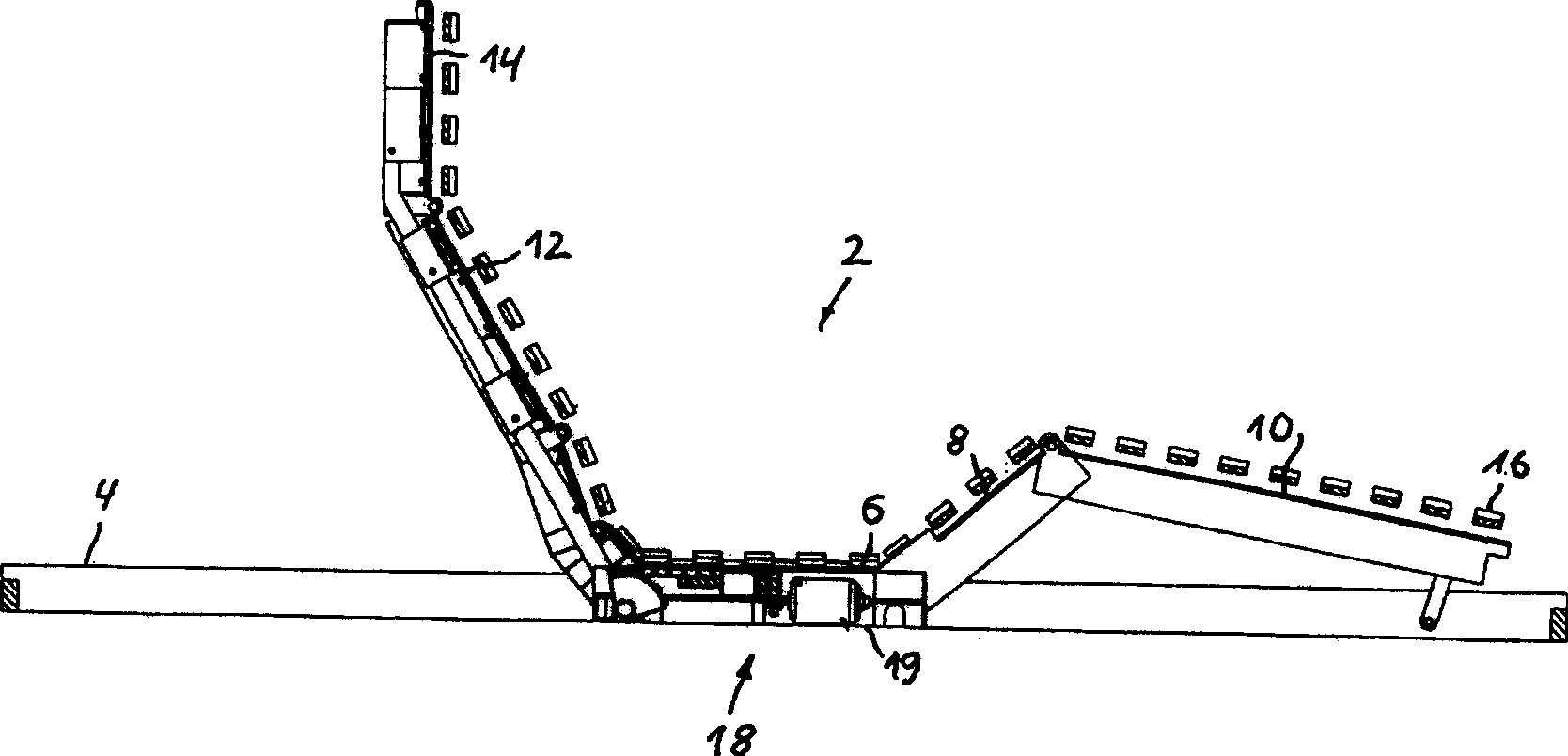
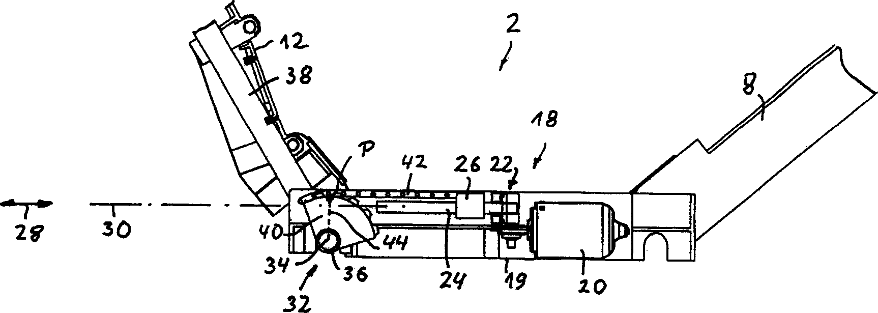
[0036] figure 1To describe an embodiment of the stent device 2 of the present invention. The carrier device 2 according to the exemplary embodiment is designed as a grid of slats and has a frame 4 to which a fixed central support part 6 is connected. A leg support 8 is rotationally connected to the central support 6 about a horizontal axis of rotation. The calf support 10 is connected to the opposite end of the leg support 8 to the middle support 6 in a rotationally flexible manner about a horizontal axis of rotation. An upper body support 12 is connected to the end of the intermediate support 6 opposite to the leg support 8 so as to rotate flexibly about a horizontal axis of rotation. A head support 14 is compliantly connected to the end of the upper body support 12 opposite to the intermediate support 6 so as to rotate about a horizontal axis of rotation. The manner in which the support members 6-14 are connected to each other is generally well known and therefore will no...


PUM


Abstract

The invention relates to an electromotive furniture drive (18) for displacing parts (6-14) of a piece of furniture relative to one another. Said drive comprises a drive means that can linearly move along a linear motion axis (30). This drive means is provided for pivoting a pivotal element, which can pivot about a pivot axis (34) and which, when the furniture drive (18) is in a mounted position, is actively connected to a part of the piece of furniture to be displaced. According to the invention, means are provided that, during the displacing motion, maintain the engagement between the drive means and the pivotal element at a point P that is essentially fixed along the linear motion axis (30). The inventive furniture drive can be easily and economically produced and has a sturdy design.

Description

field of invention [0001] The invention relates to an electric furniture drive for adjusting furniture parts relative to each other. Background technique [0002] Such furniture drives are generally known. For example, as an adjustment drive to adjust various components of a slatted grid relative to each other. [0003] A related kind of furniture transmission is known from EP 0 372 032 B1. The transmission device has a transmission mechanism for linear motion along a linear motion axis. When the furniture transmission device is in the installed position, it rotates a rotating element that is operatively connected to the furniture part to be adjusted and rotates around a rotation axis. In known furniture transmissions, the transmission mechanism of the linear movement is a main spindle nut of a main spindle transmission, and the rotating element is a rotating rod, which is rotationally connected to a rotating shaft, This axis of rotation is operatively connected to the fu...

Claims


Application Information

Patent Timeline
IPC IPC(8): A47C1/025A47C20/04A47C20/08H02K7/06
CPCA47C20/041A47C20/08
Inventor 罗尔夫·法门特约翰尼斯·施奈德
Owner 斯摩系统股份公司
Why Eureka
Try Eureka